


4-8
Power-Up
and
Testing
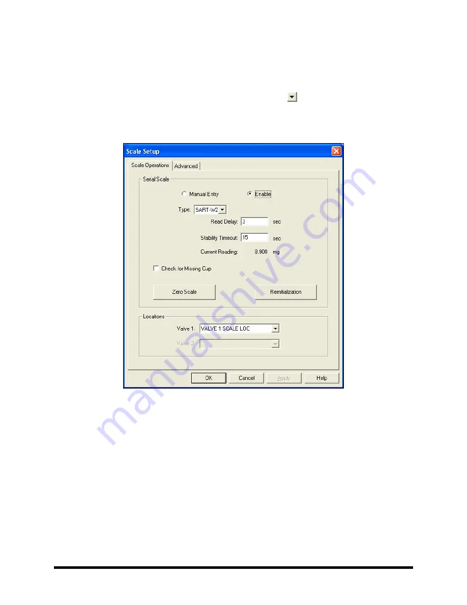
4.7.2 Scale
Setup
1.
In the FmXP Main Window, select
Configuration > Setup Scale
.
!
The Scale Setup window opens (Figure 4-7).
2.
Verify that Scale Type is SART-WZ. If not, click on the and select SART-WZ from the
drop-down list.
3.
Click on
OK
to exit the Scale Setup window.
Figure 4-7 FmXP Scale Setup
Содержание Asymtek Spectrum S-920
Страница 1: ...Spectrum Series S 920 Dispensing System Installation Operations Maintenance Manual P N 7212417 Rev A...
Страница 2: ......
Страница 4: ......
Страница 30: ...1 14 Introduction 1 10 5 Rear View Figure 1 7A Rear View 2 3 4 1 5...
Страница 124: ......
Страница 172: ...7 12 Maintenance Figure 7 7 Lubricating the X Axis Linear Guides Figure 7 8 Lubricating Y Axis Linear Guides...
Страница 185: ...Troubleshooting 8 11 Figure 8 3 FmXP Scale Setup Menu Figure 8 4 Scale Error Message...
Страница 190: ......
Страница 204: ......
Страница 208: ......
Страница 210: ......
Страница 220: ......
Страница 222: ......
Страница 223: ......
Страница 224: ......
Страница 225: ......
Страница 226: ......
Страница 234: ......


