Installation
3-20
E
1996 Nordson Corporation
All rights reserved
107 041A
Issued 1/96
Manual 12-28
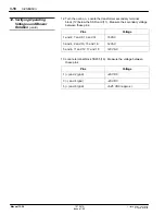
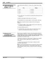
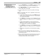
Locate terminal block TB241(17). Measure the voltage between these
pins:
Pins
Voltage
1 and 2
+12 VDC
3 and 4
+12 VDC
5 and 6
+12 VDC
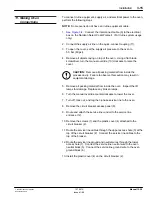
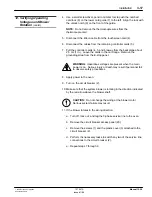
14. Turn off the oven. Turn off, lock out, and tag the 3-phase service line
to the oven.
15. Attach a wrist strap to the E-stop cover (11) ground.
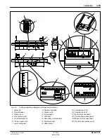
16. Install and lock the controller cards (4, 5 and 6) into the card cage.
NOTE: The connector numbers correspond to the card cage slot
numbers.
17. Connect the cables to each controller cards (4 and 5). Remove the
wrist strap from the E-stop panel (11).
18. Close the E-stop panel (11).
19. Install the blower motor access panel (19), power supply access
panel (18), and electrical access panel (17) on the oven.
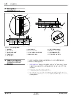
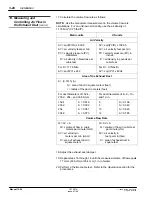
Measuring and controlling the air flow in the exhaust duct is critical for
proper operation of the oven. The procedure is simplified by taking one
reading at the center of the exhaust duct. This can be done automatically
using an Exhaust Controller or manually using either a hot-wire
anemometer or a pitot tube set-up.
The Exhaust Controller is an optional piece of equipment used with the
oven. Call your Nordson representative or distributor for more
information.
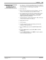
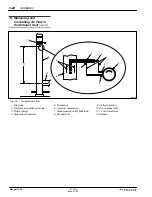
To measure the exhaust duct air flow using an incline manometer,
perform the following steps:
NOTE: This procedure assumes the use of a pitot tube, rubber or plastic
tubing, and a inclined manometer. The manometer reads air flow in
either millimeters (inches) of water or velocity in meter per minute (feet
per minute).
12. Verifying Operating
Voltages and Blower
Rotation
(contd.)
13. Measuring and
Controlling Air Flow in
the Exhaust Duct
Содержание 107 041A
Страница 1: ...Select Cure 100 Inch IR Oven Part 107 041A NORDSON CORPORATION D AMHERST OHIO D USA ...
Страница 8: ...Table of Contents vi E 1996 Nordson Corporation All rights reserved 107 041A Issued 1 96 Manual 12 28 ...
Страница 9: ...E 1995 Nordson Corporation All rights reserved Issued 11 95 12 28s1 Section 1 Safety ...
Страница 10: ...Safety 1 0 E 1995 Nordson Corporation All rights reserved Issued 11 95 12 28s1 ...
Страница 23: ...E 1996 Nordson Corporation All rights reserved 107 041A Issued 1 96 Manual 12 28 Section 2 Description ...
Страница 24: ...Description 2 0 E 1996 Nordson Corporation All rights reserved 107 041A Issued 1 96 Manual 12 28 ...
Страница 32: ...Description 2 8 E 1996 Nordson Corporation All rights reserved 107 041A Issued 1 96 Manual 12 28 ...
Страница 33: ...E 1996 Nordson Corporation All rights reserved 107 041A Issued 1 96 Manual 12 28 Section 3 Installation ...
Страница 34: ...Installation 3 0 E 1996 Nordson Corporation All rights reserved 107 041A Issued 1 96 Manual 12 28 ...
Страница 61: ...E 1996 Nordson Corporation All rights reserved 107 041A Issued 1 96 Manual 12 28 Section 4 Operation ...
Страница 62: ...Operation 4 0 E 1996 Nordson Corporation All rights reserved 107 041A Issued 1 96 Manual 12 28 ...
Страница 83: ...E 1996 Nordson Corporation All rights reserved 107 041A Issued 1 96 Manual 12 28 Section 5 Maintenance ...
Страница 84: ...Maintenance 5 0 E 1996 Nordson Corporation All rights reserved 107 041A Issued 1 96 Manual 12 28 ...
Страница 101: ...E 1996 Nordson Corporation All rights reserved 107 041A Issued 1 96 Manual 12 28 Section 6 Troubleshooting ...
Страница 102: ...Troubleshooting 6 0 E 1996 Nordson Corporation All rights reserved 107 041A Issued 1 96 Manual 12 28 ...
Страница 147: ...E 1996 Nordson Corporation All rights reserved 107 041A Issued 1 96 Manual 12 28 Section 7 Parts ...
Страница 148: ...Parts 7 0 E 1996 Nordson Corporation All rights reserved 107 041A Issued 1 96 Manual 12 28 ...
Страница 161: ...E 1996 Nordson Corporation All rights reserved 107 041A Issued 1 96 Manual 12 28 Section 8 Specifications ...
Страница 162: ...Specifications 8 0 E 1996 Nordson Corporation All rights reserved 107 041A Issued 1 96 Manual 12 28 ...
Страница 166: ...Specifications 8 4 E 1996 Nordson Corporation All rights reserved 107 041A Issued 1 96 Manual 12 28 ...

