92
34 - Scrub System, Disc
Scrub Control
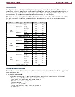
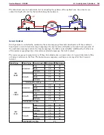
Scrub pressure is controlled by monitoring the motor amperage from both brush motors If the combined
brush motor current is below its target amperage, the deck is lowered slightly to increase brush pressure If
the combined amperage is above the target amperage, the deck is raised slightly Additionally, if either one
of the motors is operating above its maximum allowed amperage, the deck is raised
The motor amperage is sampled every 250ms, but adjustments are made only at 45 second intervals to filter
out minor variations in the floor. The instantaneous amperage readings are averaged for the 45 second
interval
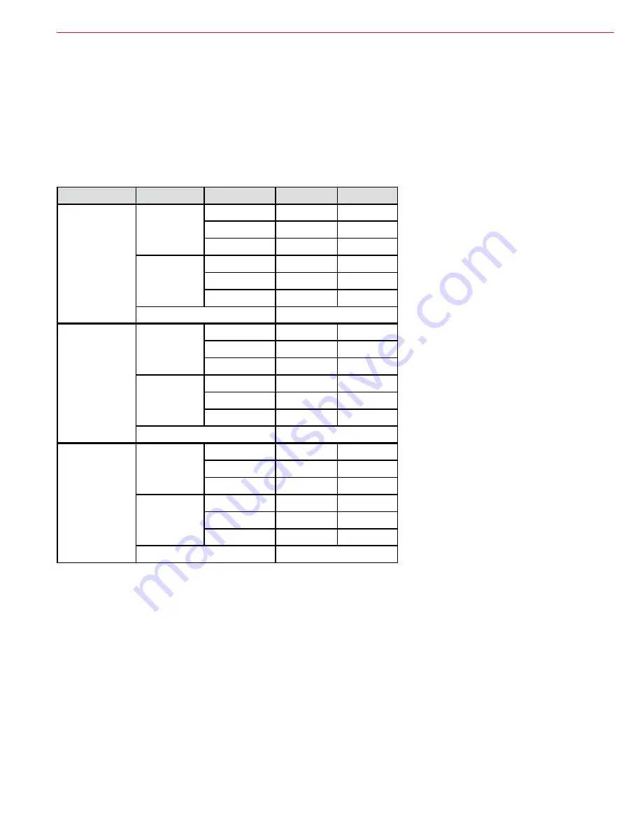
Deck Type
Floor Type
Scrub Level
Min Amps
Max Amps
34D
860D
Standard
Low
20
30
High
30
40
Extreme
40
50
Smooth
Low
15
25
High
25
35
Extreme
35
45
Individual Motor Max
25
40D
1050D
Standard
Low
20
30
High
30
40
Extreme
40
50
Smooth
Low
15
25
High
25
35
Extreme
35
45
Individual Motor Max
25
36C
910C
Standard
Low
20
30
High
30
40
Extreme
40
50
Smooth
Low
15
25
High
25
35
Extreme
35
45
Individual Motor Max
25
Operational Mode Prerequisites
Before the main controller can activate any of the operational modes, it must first check that the appropriate
prerequisites are met
•
Scrub System Outputs
– Brush Motors M1 and M2 or Deck Actuator M7 (seat switch must be closed to enter scrub mode)
◦
No scrub system fault (brush motors and actuator motor)
◦
No recovery system fault (vac motors and squeegee)
◦
Throttle command not equal to zero
◦
No Estop inhibit
◦
No impact lockout inhibit
◦ No low voltage cut out inhibit (first or second stage)
◦
No RTF inhibit

