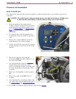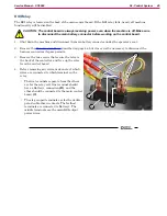
40
04 - Control System
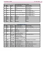
Code
Description
Comments
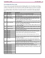
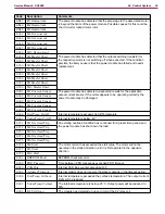
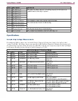
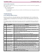
2-091
M1 HW Fault
The power module’s output is not working properly and all outputs are
disabled and the K2 relay is opened.
2-092
M2 HW Fault
2-093
M3 HW Fault
2-094
M4 HW Fault
2-095
M5 HW Fault
2-096
Parameter Change
The module’s output mode was improperly changed.
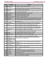
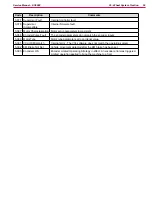
2-097
M6 Current Sensor
The current sensor has an invalid reading
2-098
M7 Current Sensor
2-101
M10 Current Sensor
2-102
Thermal Sensor
The thermal sensor has an invalid reading
2-103
K2 Coil Short
The module has detected a short to the K2 relay coil
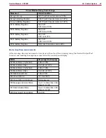
Specifications
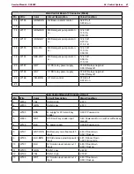
Sample Shop Voltage Measurements
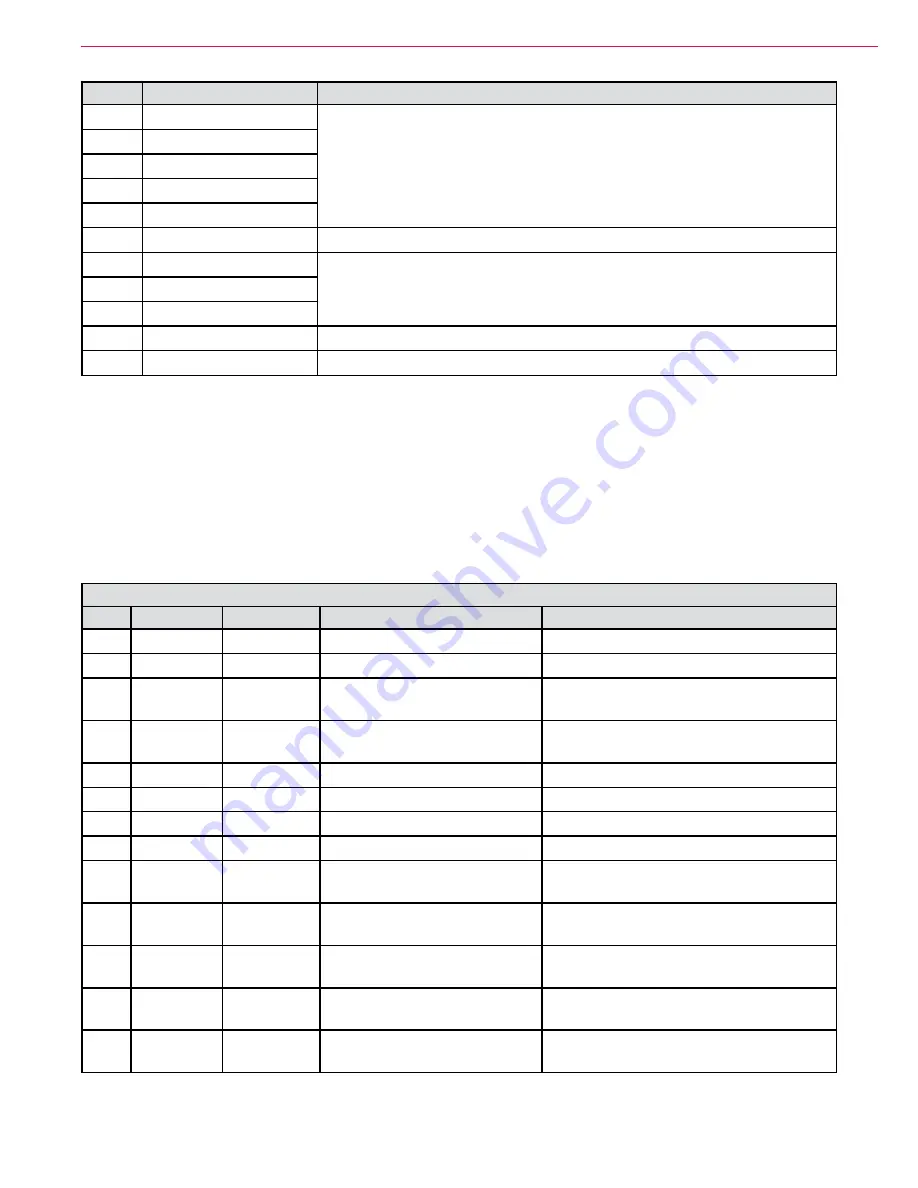
The following tables contain some “real world” shop voltage measurements to help you recognize what
“normal” looks like. All voltage values were measured with the black (Negative) voltmeter lead connected to
the main battery negative unless otherwise specified. Most outputs were turned on using the Service/Output
test function Machine battery voltage at time of testing was 37 25V
Main Control Board J1 Connector (Black)
Pin
Wire
Color
Circuit Description
Value/Condition
1
Wl59
YEL-BRN
B+ power supply
37.23V Powered on
2
WIGO
YEL-BRN
B+ power supply
37.23V Powered on
3
WI 62
ORN-BRN
K1 KSI relay control
37.2V off
0.62V on
4
W163
GRY-BLK
L1 Solution solenoid control
37.16V off
0.08V on
5
W147
BLK
B- power supply
0.001V powered on
6
W146
BLK
B- power supply
0.001V powered on
7
8
9
W142
BLK
LP1 and LP2 Headlight control
37.16V off
0.08V on
10
W178
ORN
S2 Emergency switch input
37.1V on position
0.006V Emergency shut off position
11
W245
GRN
E1 Battery charger interlock
power supply
37.16V charger NOT plugged into power
0.006V charger plugged into power
12
W175
GRN-BLU
S1 Seat switch input
37.18V operator on seat
0.175V operator off seat
13
W164
YEL-WHT
L2 DustGuard solenoid control
37.18V off
0.07V on

