77
24 - Electrical System
Working with Schematics and Diagrams
Wiring diagrams show how electrical components are connected together and to a large degree “how things
work”. However, they do not specifically show where things are located. The most common diagram is the
schematic The schematic represents the connections and interactions between components, using abstract
symbols to generically represent the components There are different forms of schematics, which vary
depending on their purpose and even type of system Schematics can be used to represent electrical systems,
hydraulic systems, pneumatic systems, or countless other interconnected systems
Navigation
In some cases it is necessary to have references across different areas of a drawing These references
can point across the drawing sheet, or to different sheets in a multi-sheet schematic The references are
commonly referred to as “Tags”. At a minimum, tags typically have a name or designation, but they may also
contain coordinate pointers to their counterpart
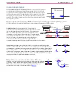
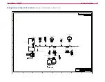
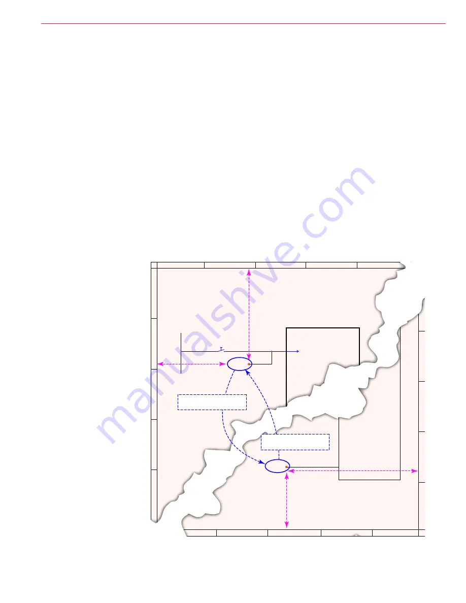
In the sample diagram below, the output from the seat switch needs to connect to the main controller on
sheet #1 and also to the drive controller on sheet #3 The identifying name could be an actual name, such as
(Seat Switch), or in this case, just a letter designator (G). Both ends of a tag will have the same identifier.
In addition to the identifier, the tag also contains coordinate information to help you locate the mating tag
faster. So the first tag contains the coordinates of the second tag, and the second tag contains the coordinates
of the first tag. The format of these coordinates are Sheet, Column, and Row.
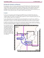
These coordinates are part
of the default title blocks on
engineering drawings, and
run around the perimeter
of the drawing sheet The
columns are represented by
the letters across the top/
bottom of the drawing, and
the rows are represented by
the numbers down the sides
of the drawing
D
C
G
F
E
D
E
A
B
C
1
2
3
4
5
SHEET 1
SHEET 3
2
3
4
5
J1-12
GRN/BLU
GRN/BLU
BLU/RED
(G) TO 3E4
S1
SW , SEAT
1
2
E2
MAIN CONTROL BOARD
INTERLOCK
E4
WHEEL-DRIVE
CONTROLLER
J4-9
GRN/BLU
(G) TO 1B2
Point Name = G to
Sheet 3 @ Coordinate E4
Point Name = G to
Sheet 1 @ Coordinate B2

