126
40 - Recovery System
Functional Description
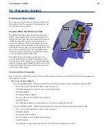
The recovery system extracts wastewater from the
floor collected by the squeegee, and deposits it into
the on-board recovery tank
Vacuum Motor and Recovery Tank
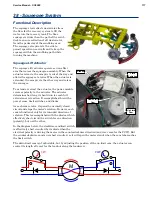
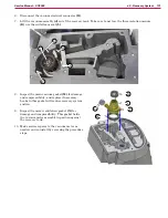
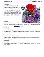
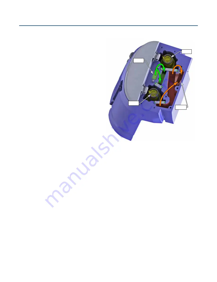
The SC6000 machine has one standard vacuum
motor, plus an optional second vacuum motor for
higher vacuum draw The vacuum motor generates
airflow through the recovery tank and suction
hose to the squeegee The high velocity air at the
squeegee pulls the wastewater off the floor and up
through the suction hose As the mixture of air and
water enters the recovery tank, the airflow slows
down due to the larger space, and the water drops
out of the airflow and into the tank.
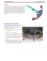
The airflow passes through an inlet screen to
prevent debris from entering the impeller of the
vacuum motor The exhaust air is expelled through
ducting in the machine toward the floor so it can be
dispersed without blowing directly on the operator
or the work environment
Operational Mode Prerequisites
Before the main controller can activate any of the operational modes, it must first check that the appropriate
prerequisites are met
•
Recovery System Outputs
– Vac motors M4 and M5 – Recovery mode (Seat switch closed upon entry) or Squeegee Actuator M6
◦
No recovery system fault (vac motors and squeegee)
◦
Throttle command not equal to zero (and not timed out)
◦
No Estop inhibit
◦
No impact lockout inhibit
◦
No low voltage cut out inhibit (second stage)
◦
No RTF inhibit
◦ Note M5 also requires Vacuum option set to dual in configuration menu
– Vac motors M4 and M5 – Wand mode (seat switch open upon entry) or Squeegee Actuator M6
◦
No recovery system fault (vac motors and squeegee)
◦
No Estop inhibit
◦
No impact lockout inhibit
◦
No low voltage cut out inhibit (second stage)
◦
No RTF inhibit
◦ Note M5 also requires Vacuum option set to dual in the configuration menu
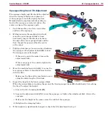
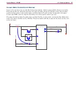
Vac 1
Vac 2
Inlet
Outlet

