42
04 - Control System
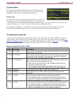
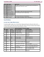
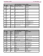
Main Control Board J2 Connector (Gray)
Pin
Wire
Color
Circuit Description
Value/Condition
14
W189
YEL
S7 Solution level sensor Lvl 3
input
4.83V Float down
0.001 Float up
15
W190
RED
S7 Solution level sensor Lvl 4
input
4.83V Float down
0.001 Float up
16
W199
YEL-RED
S3 Horn switch input
4.8V at paddle at rest
0.001V paddle pulled back
17
W198
ORN-RED
S4 Burst of power switch input
4.8V at paddle at rest
0.001V paddle pulled back
18
W200
TAN-WHT
S5 Timed solution off switch
input
4.8V at paddle at rest
0.001V paddle pulled back
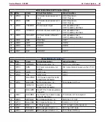
19
W204
RED
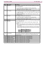
USB VBus
5.00V
20
W203
WHT
USB DM
0.005V
21
W202
GRN
USB DP
0.005V
22
23
W221
BLK
USB GND
0,001V
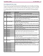
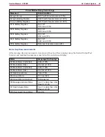
Power Module J3 connector
Pin
Wire
Color
Circuit Description
Value/Condition
1
W013
ORN-GRY
M7 Deck ac or -
35.5V - up, 3.0V down
2
W019
BRN
K2 Power module relay coil
control
36V momentarily at power up, then 11.4V
3
W196
GRN
CAN 1 Low
2.44V
4
W193
YEL
CAN 1 High
2.57V
5
BLU-PINK
+15V power output for Curtis
programmer connector
6
W014
BLU-GRA
M7 Deck ac or -
37.6V down, 0.07V up
7
GRN-VIO
Serial RX for Curtis
programmer connector
8
BLU-GRN
Serial TX for Curtis programmer
connector
9
W247
BLU-RED
Key Switch Input power supply
(from K1 KSI relay)
37.66V when K1 is energized
10
W225
WHT-BLK
M10 Optional Pump + or -
35.6V on, 1.11V off
11
W170
BLU-ORN
M10 Optional Pump + or -
0.004V on, 1.11V off
12
W122
BLK
B- Power supply
1.1V no load or with vacuum on
13
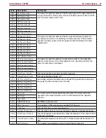
W011
TAN-BLU
M6 Squeegee ac or _
34.5V up, 3.0V down
14
W010
BLK-GRA
M6 Squeegee ac or _
37.6V down, 0.05V up

