22
Installation and quick start commissioning guide - Commander ID300/302
5511 en - 2017.06 / a
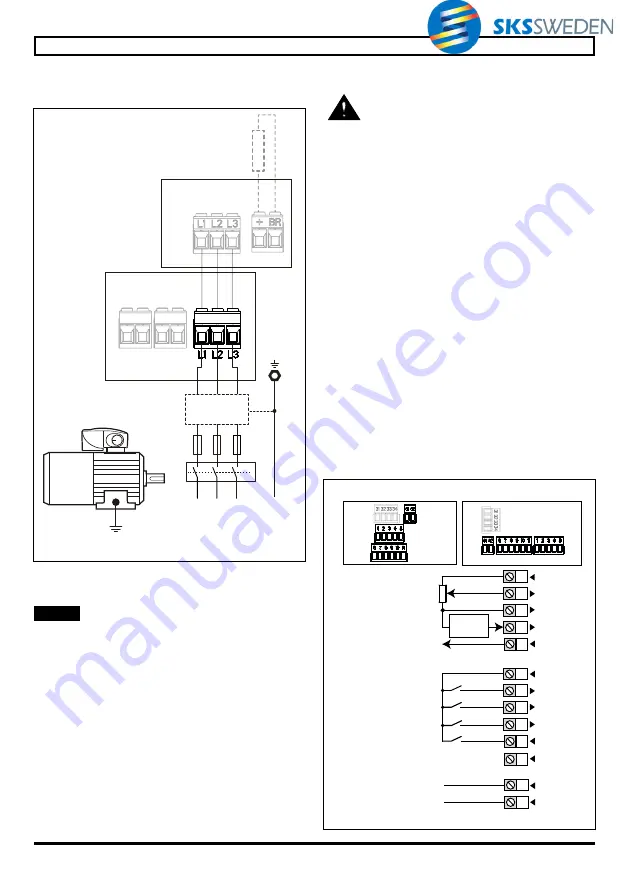
CONNECTIONS
•
Dedicated brake motor power connections with
ID-SIZEx-Brake contactor option
L1
PE
L2
L3
+ -
++ -
Optional
braking resistor
(1)
Brake DC supply
(already wired)
Already wired
Optional
EMC filter
Fuses
Mains supply
(3 phases)
Supply
ground
Ground
connection
Drive AC Power
connectors
ID-SIZEx-Brake Contactor
connectors
(1)
A thermal overload protection device is included as
standard in the optional braking resistors.
NOTE
FFB brake power connections (DC coil, 180Vdc) are
already wired at factory by using the relevant connector
(“+,-” for 400V supply). The brake motor is pre-wired to
ease commissioning.
3.6 -
Control connections
•
The control circuits are isolated from the
power circuits in the Commander ID300/302 by
single insulation only. The installer must
ensure that the external control circuits are insulated
from human contact by at least one layer of insulation
(supplementary insulation) rated for use at the AC
supply voltage.
•
If the control circuits are to be connected to o ther
circuits classified as Safety Extra Low Voltage (SELV)
(e.g. to a personal computer), an additional isolating
barrier must be included in order to maintain the SELV
classification.
•
If any of the digital inputs (including the drive enable or
STO inputs) are connected in pa rallel with an inductive
load (i.e. contactor or motor brake) then suitable
suppression (i.e. diode or varistor) should be used on
the coil of the load. If no suppression is used then over
voltage spikes can cause damage to the digital inputs
and outputs on the Commander ID300/302.
• When the Commander ID300/302 is controlled
remotely, avoid parallel routing of power cables and
control cables.
•
Ensure the logic sense is correct for the control circuit
to be used. Incorrect logic sense could cause the motor
to be started unex pectedly. Positive logic is the state
for the Commander ID300/302.
• Check that the terminal blocks have been removed
from their fixed holder (unplugged) before making any
connections, so as to avoid putting pressure on the
card.
3.6.1 - Wiring layout
4
5
1
2
3
41
42
+10 V
ADI1
ADI2
ADIO3
10k
Ω
0V
9
10
6
7
8
+24V
DIO1
DI3
DI4
DI2
11
+24V
Voltage frequency
reference
(1)
Routed to red, green,
and yellow LEDs
(3)
Run reverse/Stop
(4)
Run forward/Stop
(4)
Drive enable
Drive OK
Size 1
or 2
Commander ID300 Control wiring
Size 3
Relay
(Over-
voltage
cat. II)
ADI1 / ADI2
reference select
Current frequency
reference
(2)
Current
signal


