Page 94/ 191
11.4 Junction box
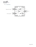
11.4.1 Grounding of cables and junction box
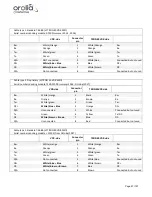
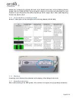
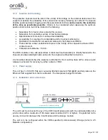
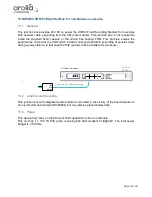
Please note that your connections may differ from pictures below, see
paragraph ‘Wire schematic’.
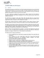
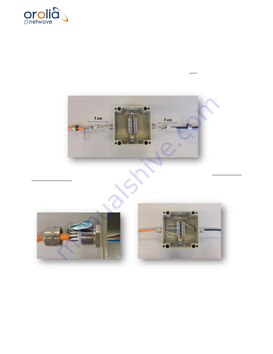
It is important that the grounding shields of the cables (of TRON 40VDR and VDR) are in contact
with the cable glands of the junction box. Therefore, firstly strip off 7 cm of the cables to create 7
cm of grounding shield. Separate the grounding shields from the cables. Do not remove the
grounding shields.
Place the grounding shields over the screw-threads and enclose the cable glands on both sides
of the junction box. In this way the grounding shields are connected to the metal cable glands.
Note:
by reopening the cable glands, the grounding shields will break, and the cable needs to
be stripped off again.
Содержание NW6000
Страница 1: ......
Страница 91: ...Page 91 191...
Страница 92: ...Page 92 191...
Страница 116: ...Page 116 191 Figure 16 4 2 Connection figure NMEA Module 16 channels Figure 16 4 3 Connection table NMEA Modules...
Страница 120: ...Page 120 191 Figure 17 4 2 Connection figure Digital Module 16 channels...
Страница 121: ...Page 121 191 Figure 17 4 3 Connection figure Digital Module 24 channels...
Страница 125: ...Page 125 191 Figure 18 4 2 Connection figure Analogue Module 8 channels...
Страница 126: ...Page 126 191 Figure 18 4 3 Connection figure Analogue Module 12 channels...
Страница 184: ...Page 184 191 Figure 5 8 1 Sample dataset playback...


