Page 77/ 191
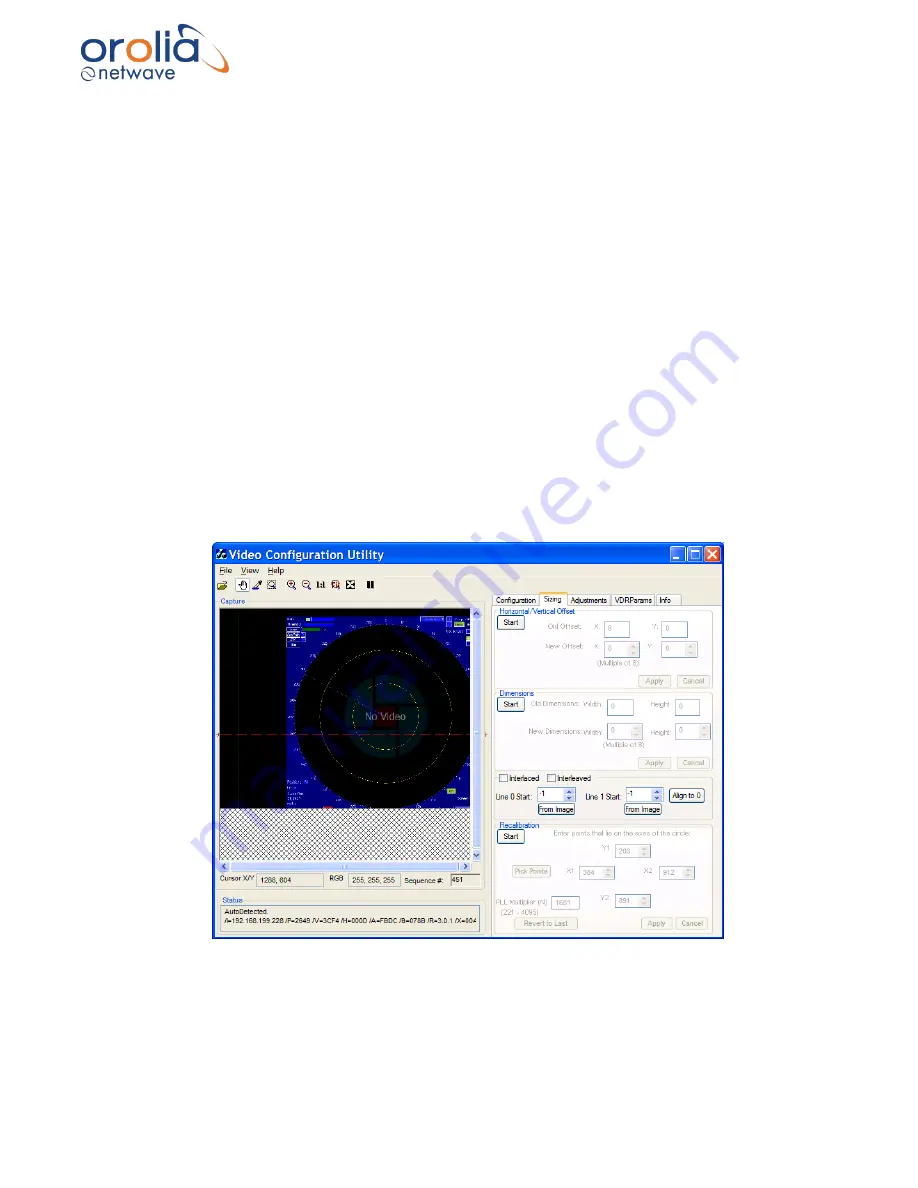
First, locate a circle in the radar image in the Capture window. A Variable Range Marker (VRM)
or range ring, available on most radar images, provides effective circles for assessing
recalibration. If the image requires recalibration the ring will appear more oval than round. In that
case it is necessary to recalibrate the image by setting the proper aspect ratio.
1.
To begin recalibration, click the Sizing Tab which opens the Sizing page.
2.
Click the Start button in the
Recalibration
section at the bottom of the Sizing page.
3.
In the Capture window click and drag a rectangle around the circle OR click the
Pick
Points
button to select the points of the circle in order. (Picking points may be easier.).
4.
When 4 points of the circle are selected by either method above, click the Apply button.
5.
This applies the adjusted value of the Phase Lock Loop PLL Multiplier Number (N) and
recalibrates the captured image.
6.
If the recalibrated image has improved but needs further recalibration, click and drag a
rectangle around the circle, OR click the Pick Points button to select the points of the
circle in order. (Picking points may be easier.).
7.
When 4 points of the circle have been chosen, by either method above, click the Apply
button.
8.
This will apply the newly re-adjusted value of the PLL Multiplier Number (N).
9.
If the circle in the newly recalibrated image appears more oval than in step vi, click Start
to begin again.
10.
Click
Revert to Last
to reset to the previous value of the PLL Multiplier (N).
11.
Click Apply and repeat this procedure from step iv.
Figure 10.20.2 - Correct aspect ratio after recalibration
12.
The Image Offset of the captured image will need to be re-adjusted.
Follow the steps above: Horizontal/Vertical Offset to adjust the upper left corner of the
image.
Содержание NW6000
Страница 1: ......
Страница 91: ...Page 91 191...
Страница 92: ...Page 92 191...
Страница 116: ...Page 116 191 Figure 16 4 2 Connection figure NMEA Module 16 channels Figure 16 4 3 Connection table NMEA Modules...
Страница 120: ...Page 120 191 Figure 17 4 2 Connection figure Digital Module 16 channels...
Страница 121: ...Page 121 191 Figure 17 4 3 Connection figure Digital Module 24 channels...
Страница 125: ...Page 125 191 Figure 18 4 2 Connection figure Analogue Module 8 channels...
Страница 126: ...Page 126 191 Figure 18 4 3 Connection figure Analogue Module 12 channels...
Страница 184: ...Page 184 191 Figure 5 8 1 Sample dataset playback...


