SL2100 GETTING STARTED GUIDE
57
2.6.7
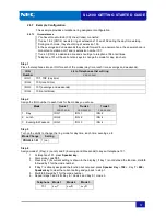
Example Configuration
This example provides a telephone ring assignment configuration.
2.6.7.1
Circumstances
You have three Outside (CO) lines (trunks) connected.
Trunks 1 & 2 (CO1/2) needs to ring at extensions 101 and 102 during the day time working.
During lunch mode, they should ring at extension 105.
In the evenings and on weekends they should forward to an answer phone, the answer phone is
connected to station port 7 and is extension number 107.
Trunk 3 (CO3) is a dedicated line and should go to telephone 106 at all times.
Telephone 101 will have Function keys to change the mode for day, lunch etc.
Step 1
Place the telephones into an IRG for each of the modes (day time, lunch time, evenings and weekends).
IRG
Number
List of telephones that will ring
PRG 22-04-01
IRG 1
101
,
102
(day time)
IRG 2
105 (lunch time)
IRG 3
107 (evenings and weekends)
IRG 4
106 (at all times)
Step 2
Assign the IRG number to each trunk for the modes you will use.
Mode
Trunk 1
PRG 22-05-01
Trunk 2
PRG 22-05-01
Trunk 3
PRG 22-05-01
1 Day
IRG 1
IRG 1
IRG 4
2 Lunch
IRG 2
IRG 2
IRG 4
3 Evening & Weekend
IRG 3
IRG 3
IRG 4
Step 3
Turn on the ability to change the ring mode for day time, lunch time, evenings, etc.
Mode Change
Setting
PRG20-07-01
1 (on)
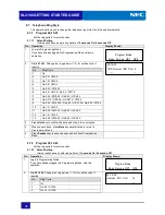
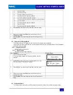
Step 4
Assign modes 1 (Day), 2 (Lunch) and 3 (Evenings and Weekends) to keys at telephone 101.
1. At telephone 101, press
Speaker key
.
2. Dial service code
751.
3. Press Key 7 (Its current setting is shown in the display). If Key 7 is not defined the function, dial
09
followed by
1
for the mode number.
4. If Key 7 is already assigned the function but not used, press
Speaker Key
+
752
+ .Key
7
+
000
+
Speaker key
to clear the current setting and go back to step 1.
5. Dial
09
followed by
1
for the mode number.
6. Repeat steps 3 and 4 for Key 8 = mode 2 and Key 9 = mode 3.
Telephone Mode 1
Mode 2
Mode 3
101
Key
7
Key
8
Key
9
Содержание UNIVERGE SL2100
Страница 18: ...SL2100 GETTING STARTED GUIDE 14 MEMO...
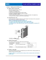
Страница 23: ...SL2100 GETTING STARTED GUIDE 19 1 7 System Connection Diagram Figure 1 1 shows a system connection diagram...
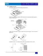
Страница 48: ...SL2100 GETTING STARTED GUIDE 44 5 Attach the phone to the wall...
Страница 77: ...SL2100 GETTING STARTED GUIDE 73 MEMO...
Страница 78: ...Getting Started Guide NEC Corporation Issue 1 0...

