background image


SL2100 GETTING STARTED GUIDE 


45 

Section 6  Starting Up the SL2100 system 


6.1  Before starting up the system 

Before starting up the system, make sure: 

• Chassis are installed correctly. 


• All extensions are cabled correctly.


• All earth ground and PSTN 

trunks are cabled correctly.   

• All boards are configured, equipped and secured correctly.


• AC power cord is cabled 

correctly. 

• At least one display type 

multiline telephone is connected to the system. (for programming) 

• 

The Lithium battery is installed on the CPU-C1 board correctly. 


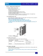
6.2  Plug the AC power cord 

The AC power inlet is located at the back side of each chassis. The AC power cord is connected to 

the AC inlet and the commercial AC power socket.


!! Before connecting the AC power cord, make sure: 

• The power switch at the left side of each 

chassis is turned OFF. 

• The power switch at the commercial AC power 

socket is turned OFF. 

• The AC plug fits the commercial AC power socket. The plug adapter is

 necessary if it 

does not fit.


6.3  Starting Up the System 

There are two methods for startup (COLD Start and HOT Start).


Start Up Method


Description


Purpose


COLD Start 

The factory setting data is loaded. 

First time start up 

System Initialization 

HOT Start 

The customer setting data is loaded. 

System Reboot 


6.4  Perform a COLD Start 

This section describes the process for starting the system for the first time or starting a system that 

requires the customer data be deleted. 


!! System software is loaded from flash memory, and the customer data is deleted from 

RAM memory.


Содержание UNIVERGE SL2100

Страница 1: ...100 Telephone System including the Outside CO line and telephone connections This Getting Started Guide will cover the most frequently used configuration options Only the SL2100 Main chassis is includ...

Страница 2: ...at any time without notice NEC Corporation has prepared this document for use by its employees and customers The information contained herein is the property of NEC Corporation and shall not be reprod...

Страница 3: ...Mounting the Chassis 26 3 2 1 Wall Mounting Procedure 28 3 3 Connecting Earth Ground 30 3 4 Connect AC power cord 30 Section 4 Installing the CPU board and other option board 31 4 1 Mount the CPU boa...

Страница 4: ...ng Assignment 55 2 6 7 Example Configuration 57 2 7 Telephone Ring Style 58 2 7 1 Program 20 15 01 58 2 7 2 Program 20 15 03 58 2 8 Internal Call Ringing Mode 59 2 8 1 Program 20 02 12 59 2 9 Extensio...

Страница 5: ...s will not be held responsible The goal is to produce a comprehensive and accurate manual However if errors or omissions are found in this manual please notify NEC Corporation If the system requires i...

Страница 6: ...ing to or from the system the main power source or any peripheral equipment It might cause a fire an electrical shock or a system failure If the wiring is damaged contact the dealer Correctly insert a...

Страница 7: ...p and water If battery acid contacts the eyes flush the eyes with water In either event seek medical attention If there is battery acid on a cloth use water to wash the battery acid from the cloth Do...

Страница 8: ...sed to Electromagnetic Interference EMI from devices such as television sets and two way radios Locations that receive illegal electric waves The life expectancies of the system and the main power sou...

Страница 9: ...urge limiting capacitor and resistor on the air conditioner s electromagnetic switch s coil It might be necessary to adjust the ventilation so the air conditioning is equally effective throughout the...

Страница 10: ...need to be replaced on a periodic basis In the event of sudden traffic a part that is past due for replacement might lead to a system failure and damage to the system A service contract with the deale...

Страница 11: ...of the FCC Rules These limits are designed to provide reasonable protection against harmful interference in a residential installation This equipment generates uses and can radiate radio frequency ene...

Страница 12: ...n of the number of devices that may be connected to a line as determined by the total RENs contact the local telephone company The REN for this product is part of the FCC Registration Number or produc...

Страница 13: ...l repairs must be performed by an authorized agent of NEC Corporation of America The user requiring service is responsible for reporting the need for service to an NEC Corporation of America authorize...

Страница 14: ...TION The use of monitoring recording or listening devices to eavesdrop monitor retrieve or record telephone conversations or other sound activities whether or not contemporaneous with transmission may...

Страница 15: ...on de conformit et indique que les sp cifications techniques d ISED ont t respect es Il n implique pas qu ISED a approuv le mat riel Notice The Ringer Equivalence Number REN for this terminal equipmen...

Страница 16: ...ALED LEAD BATTERIES LITHIUM SEALED LEAD BATTERIES MUST BE COLLECTED RECYCLED OR DISPOSED OF IN AN ENVIRONMENTALLY SOUND MANNER The incineration landfilling or mixing of sealed lead batteries with the...

Страница 17: ...human health and the environment Please be informed that a fine may be imposed for illegal disposal of electrical and electronic products via the general municipal waste stream To facilitate separate...

Страница 18: ...SL2100 GETTING STARTED GUIDE 14 MEMO...

Страница 19: ...dware Manual separate issue for the details General Information The SL2100 system is a progression from SL1000 SL1100 system and is newly provide a legacy and IP communication system for All In One Sm...

Страница 20: ...ompt 1 language Enable to use multi language voice prompts when optional hardware IP7WW SDVMS C1 IP7WW SDVML C1 is installed Up to 26 languages are provided VRS Voice Mail Recording Storage 2 hours Yo...

Страница 21: ...Digital Ext Port by PoE Only by Digital Ext Port Color Line Up Black Only Black Only Black Only Black Only LCD 24 digits x 3 lines w Backlit 24 digits x 3 lines w Backlit 168 x 128 Dots w Backlit Numb...

Страница 22: ...source user provided per system The Audio In in the music resource is connected to the Audio In of RL Audio port on the 082U B1 1 5 External Paging You can connect three external paging devices user...

Страница 23: ...SL2100 GETTING STARTED GUIDE 19 1 7 System Connection Diagram Figure 1 1 shows a system connection diagram...

Страница 24: ...FE C1 board on Expansion Chassis Supports VRS VM InMail channels expansion Up to 16ch Additional 48 Telephony resources DTMF Dial tone Busy tone FSK caller ID receiver sender Support Analog Modem V 34...

Страница 25: ...C1 daughter board is mounted on the 082U B1 008U C1 or 000U C1 board and installed on the Universal slot in the IP7 4KSU C1 chassis and provides either an ISDN Primary Rate Interface T1 Interface or E...

Страница 26: ...ole gives a 2 wire Digital multiline terminal user a Busy Lamp Field BLF and one button access to extensions trunks and system features Mainly designed for operator use the 60 button DSS console provi...

Страница 27: ...connectors etc 11 Secure the cables 12 Connect the AC cord and power up the SL2100 system 15 Install optional Items 1 1 1 Confirm the Installation Location The Installation location must be confirmed...

Страница 28: ...You will need an RJ11 socket for each SL2100 system phone and DSS console Some of the wiring may be required for the modifications Move the exchange lines analog telephones one at time and test each...

Страница 29: ...jack is specifically designed for wet locations Never touch uninsulated telephone wires or terminals unless the telephone line is disconnected at the network interface To avoid damage the chassis sho...

Страница 30: ...lexes microwaves air conditioners etc Near radio antennas including shortwave Section 3 Installing the Chassis When installing the chassis always wall mount it Before installing the chassis the wall w...

Страница 31: ...ling three chassis in your system NEC strongly recommend centering the main chassis to accommodate the maximum length of the extension cable If you do not center the main chassis the cable may not rea...

Страница 32: ...Arrangement 3 2 1 Wall Mounting Procedure 1 Use the attached template and put on the wall to mark the four screw positions 2 Install three screws 1 3 into the wall The screw heads must stand off from...

Страница 33: ...rews M4 1x 25 4 pcs are attached to the Chassis Another screw is installed after slide the chassis into the position 3 Align the three holes on the back of the Chassis with the three screws installed...

Страница 34: ...Each chassis in the system must be grounded separately using the procedure listed below 1 Loosen the screw 2 Insert a grounding wire supplier provided 3 Tighten the screw 4 Connect the grounding wire...

Страница 35: ...are hot swappable Do not remove or install from the chassis when powering up 2 Insert a CPU C1 board in the guide rail of chassis and push it securely into position and tighten the two screws on the...

Страница 36: ...g up 1 Ensure the Chassis are powered off and unplug the AC cord 2 Use micro nipper to cut and remove the plastic knockouts as required for each expansion interface board slot For your safety smooth t...

Страница 37: ...s and pull out the 082U 008U board 2 Use micro nippers to cut and remove the specified plastic knockout on the 082U 008U 000U board For your safety smooth the cut edges after removing the plastic knoc...

Страница 38: ...he CPU board 1 Ensure the Chassis are powered off and unplug the AC cord 2 Loosen two screws and pull out the CPU board if the CPU is installed 3 Use micro nippers to cut and remove the plastic knocko...

Страница 39: ...E 35 4 1 When both VOIPDB C1 and EXIFB C1 boards are mounted on the CPU board refer to the following installation 5 Insert the CPU board in the guide rail of chassis and push it securely into position...

Страница 40: ...the cable near any high frequency generating equipment Use cable protectors if the cables are run on the floor Aerial distribution wiring is not allowed Maximum cable lengths are listed in the followi...

Страница 41: ...ard The board provides RJ61 modular jack labeled ESI 1 4 5 8 for extension connections 1 Insert the modular plugs of the extension line cords 2 wire 4 wire into the extension modular jacks on the 082U...

Страница 42: ...1 2 082U B1 HYB SLI 1 2 3 4 5 6 7 8 008U C1 for the extension connections 1 Insert the modular plugs of the extension line cords 2 wire into the extension modular jacks on the 082U B1 008U C1 board S...

Страница 43: ...IP Multiline Terminal is connected to the VoIPDB C1 board through PoE HuB Using LAN cable to connect VoIPDB and IP Multiline Terminal through PoE HuB CPU C1 VoIPDB C1 PoE HUB LAN Cable LAN Cable PoE H...

Страница 44: ...analog trunk modular jacks on the board 3COIDB Pin No Pin Function COI 1 3 1 Not Used 2 CO 3 Tip 3 CO 2 Tip 4 CO 1 Ring 5 CO 1 Tip 6 CO 2 Ring 7 CO 3 Ring 8 Not Used Ensure that you connect the 2 wir...

Страница 45: ...Low Position Setting 1 Turn telephone over button side down 2 Adjust the legs to desired height 3 Lead the line and handset cords through the applicable grooves 4 Turn telephone over button side up 2...

Страница 46: ...Multiline Terminal 1 Arrange the cables and put down the leg as shown below 2 Remove the hook switch hanger and Insert the hook switch hanger in the slot below the hook switch 3 Install two screws in...

Страница 47: ...eg as shown below 2 Attach the IP4WW WALL MOUNT UNIT Optional to the bottom panel and arrange the cables as shown below 3 Remove the hook switch hanger and Insert the hook switch hanger in the slot be...

Страница 48: ...SL2100 GETTING STARTED GUIDE 44 5 Attach the phone to the wall...

Страница 49: ...inlet and the commercial AC power socket Before connecting the AC power cord make sure The power switch at the left side of each chassis is turned OFF The power switch at the commercial AC power socke...

Страница 50: ...When the system has completed reloading the software about one minute the RUN LED flashes green on the CPU board and the connected multiline telephone s display will shows the time and date and exten...

Страница 51: ...the line cord supplied with the phone 7 2 Test the Analog Terminals Test each phone in turn 1 Lift the handset If you hear system dial tone the phone has working correctly If you do not hear dial tone...

Страница 52: ...Trunk Access Code 003 Trunk Number If you hear an exchange dial tone the line is working correctly If you do not hear an exchange dial tone check the connections from the outside CO line to the SL210...

Страница 53: ...yed on function key 1 12 with busy lamp indication The Pilot number for voice mail is 3999 Mailbox numbers 1 64 are assigned as personal mailboxes for Extensions 101 164 1 2 Before you Begin Before yo...

Страница 54: ...s the Mute key several times to returns the previous screen 2 Enter the Program Number e g 10 01 01 If you dial an incorrect Program Number you can returns the previous screen by pressing the Mute key...

Страница 55: ...allows you to enter a new program beginning with 1 Pressing Mute one last time brings you to the beginning program display allowing you to enter any program number DND Switch between the different in...

Страница 56: ...the next option 6 Enter the two digits of the minutes 00 59 Press Hold key to confirm the entry and step to the next option 7 Enter the two digits of the seconds 00 59 Press Hold key to confirm the en...

Страница 57: ...ange line to provide different ring assignments throughout the day 2 6 2 1 Default Setting Each Line e g CO1 CO3 is assigned to incoming Ring Group IRG number 1 There are up to eight settings availabl...

Страница 58: ...Day Night mode Option 2 6 4 1 Default Setting Day Night modes can not be changed using telephones No Operation Display Shows 1 Log into Programming Mode If you have already logged into Programming Mod...

Страница 59: ...ress the Programmable Function Key you want to set its current setting is shown in LCD display If the key is not defined the function go to step 5 4 If the Function Key is already assigned the functio...

Страница 60: ...Configuration mode Keys are changed by dialing a Service Code at the telephone You will need a separate key for each mode you are using The key for the current mode lights red To change the mode pres...

Страница 61: ...IRG 2 105 lunch time IRG 3 107 evenings and weekends IRG 4 106 at all times Step 2 Assign the IRG number to each trunk for the modes you will use Mode Trunk 1 PRG 22 05 01 Trunk 2 PRG 22 05 01 Trunk 3...

Страница 62: ...0 10 On 1 0 Off 4 0 11 On 0 25 Off 0 25 On 0 25 Off 4 25 12 On 1 0 Off 3 0 13 On 0 25 Off 0 25 On 0 25 Off 2 25 3 Press Hold key to confirm the entry and step to the next option 4 When you are done pr...

Страница 63: ...one or voice announce where the caller can speak directly to the loudspeaker of the phone they are calling 2 8 1 Program 20 02 12 Set the mode for Internal calls 2 8 1 1 Default Setting The default se...

Страница 64: ...ber The TAM number is then given the access properties for each of the exchange lines 2 10 1 Program 15 06 01 Use this program to give the telephones a trunk access map TAM number There are 128 TAM nu...

Страница 65: ...an overwrite the current entry 0 No access 1 Outgoing only 2 Incoming only 3 Retrieve held call only 4 Outgoing and retrieve held call 5 Incoming and retrieve held call 6 Incoming and outgoing 7 Incom...

Страница 66: ...eed to turn on Caller ID for each of the analog telephones that are Caller ID compatible 2 11 1 Program 14 02 10 Program 15 03 09 Turn on Caller ID for each Analog trunk 2 11 1 1 Default Setting The d...

Страница 67: ...analog telephones that you have connected 2 12 1 Program 82 04 0x Set the system to detect a recall duration of 105ms to 1000ms You will need to change three options within this program The SL2100 wi...

Страница 68: ...ions for each group How the calls will ring around the group either in a set order of priority or randomly at any telephone Try each telephone once or keep hunting your call can ring at each available...

Страница 69: ...ss Hold key to confirm the entry and step to the next option 3 When you are done press Mute key several times to return to Programming Mode 4 Press Speaker key to save changes and exit if you are fini...

Страница 70: ...cate Data The entry will be removed and you can enter a new number 3 When you are done press Mute key several times to return to Programming Mode 4 Press Speaker key to save changes and exit if you ar...

Страница 71: ...telephones are in a paging group No Operation Display Shows 1 Log into Programming Mode If you have already logged into Programming Mode skip this operation 2 Dial 31 02 01 For each telephone enter th...

Страница 72: ...l 90 68 01 Enter the trunk number 1 128 3 Press the Hold key and the automatic line adjustments will start Note While this test is being performed the system will not be operational 4 Once the test is...

Страница 73: ...the IP addresss of the SL2100 system If a DHCP server does not exist refer to the following chart 3 When the WebPro Login Screen is displayed enter the User Name and Password using PRG90 02 System Min...

Страница 74: ...When the WebPro home page displays click the System Data icon to access the Programming Mode e g PRG10 01 5 You can change any value in Time and Date Setup PRG10 01 for example from the default Click...

Страница 75: ...SL2100 GETTING STARTED GUIDE 71 6 For other programming click the corresponding program number from the PRG menu left hand side 7 Click Log out icon to logout of Web Programming...

Страница 76: ...e wiring will be shown as followings 1 Digital 2W Multiline Terminal RJ 61 Pin out Channel No ESI 1 ESI 5 ESI 2 ESI 6 ESI 3 ESI 7 ESI 4 ESI 8 Signal L1 Tip L2 Ring L1 Tip L2 Ring L1 Tip L2 Ring L1 Tip...

Страница 77: ...SL2100 GETTING STARTED GUIDE 73 MEMO...

Страница 78: ...Getting Started Guide NEC Corporation Issue 1 0...

Отзывы: