General Description 2-17
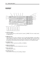
LEDs
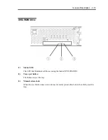
POWER LED
The POWER switch of the CPU/IO module has an in-built LED. If the AC power is supplied, the
LED of the primary POWER switch illuminates (only the primary POWER switch functions). Also,
the CPU/IO module has the POWER LED to show the status of the module power status.
CPU/IO Module POWER LED
LED indication
Description
Action
Not on
Power supply is off.
Check that the status LED 1
on both CPU/IO modules is
powered off, and then press
the POWER LED to power on
the system.
On
Power supply is on.
CPU/IO Module Status LED 1, 2
There are two kinds of LEDs that indicate the module status on the front and back sides of the
CPU/IO module. The display combination of the two LEDs indicates the CPU/IO module status.
Status
LED1
Status LED2
Description
Action
Not on
Power supply is off.
When the system is starting, the
initialization process is performed.
Wait for a while; the LED
will illuminate in green.
Blinking in
green
If the OS is running, duplex
configuration is not made for one
of the components in the CPU/IO
modules.
Check that the cable is
firmly connected. If the LED
does not illuminate in green
after a while, record the
status LED status, and
contact a maintenance
service company.
Not on
Green
The device is duplexed and
running normally.
After the AC power is supplied, the
device running in the standby
power mode is being initialized.
Wait for a while. The status
LED 1 will be powered off,
and the POWER switch will
be enabled.
When the system is starting, the
initialization process is performed.
Wait for a while; the status
LED 1 is powered off.
Amber
Not on
When the OS is running, the
CPU/IO module has a problem.
Check that the cable is
firmly connected. If the LED
does not illuminate in green
after a while, record the
status LED status, and
contact a maintenance
service company.
Содержание EXP320J
Страница 12: ... THIS PAGE IS INTENTIONALLY LEFT BLANK ...
Страница 25: ...xiii APPENDIX A SPECIFICATIONS A 1 APPENDIX B I O PORT ADDRESSES B 1 ...
Страница 26: ...xiv THIS PAGE IS INTENTIONALLY LEFT BLANK ...
Страница 28: ...1 2 Precautions for Use 使用上的注意 本章包含著對服務器恰當安全的操作必要的信息 ...
Страница 54: ...1 28 Precautions for Use This page is intentionally left blank ...
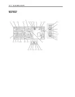
Страница 64: ...2 10 General Description Rear View ...
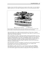
Страница 68: ...2 14 General Description CPU IO Module CPU IO module ...
Страница 88: ...2 34 General Description This page is intentionally left blank ...
Страница 100: ...3 12 Windows Setup and Operation 3 Confirm that RDR of the disk is cancelled ...
Страница 101: ...Windows Setup and Operation 3 13 4 Cancel the disk of the corresponding slot in the same manner ...
Страница 218: ...4 92 System Configuration This page is intentionally left blank ...
Страница 253: ...Installing and Using Utilities 5 35 DIMM Allows the information of DIMM on the CPU modules to be viewed ...
Страница 390: ...5 172 Installing and Using Utilities This page is intentionally left blank ...
Страница 408: ...6 18 Maintenance 3 Stop of PCI module 1 4 Start of PCI module 1 ...
Страница 410: ...6 20 Maintenance This page is intentionally left blank ...
Страница 454: ...7 44 Troubleshooting This page is intentionally left blank ...
Страница 485: ...System Upgrade 8 31 board must not be mixed with N8804 005 or N8803 035 ...
Страница 500: ......
Страница 503: ......

