© National Instruments
|
1-21
NI cDAQ-9132/9133/9134/9135/9136/9137 User Manual
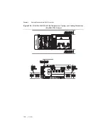
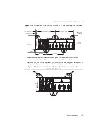
Figure 1-11.
NI cDAQ-9133/9135/9137 Temperature, Cooling, and Cabling Dimensions
(NI cDAQ-9135 Shown)
Caution
Your installation must meet the following requirements for space and
cabling clearance, as shown in Figures 1-10 and 1-11:
•
Allow 25.4 mm (1.00 in.) on the top and the bottom of the controller for air
circulation.
•
Allow 50.8 mm (2.00 in.) in front of modules for cabling clearance for common
connectors, such as the 10-terminal, detachable screw terminal connector.
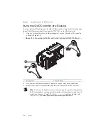
Mounting the cDAQ Controller on a Panel
Directly mounting the cDAQ controller to a rigid surface is the only recommended method for
applications that are subject to high shock and vibration.
You can mount the cDAQ controller without a kit by screwing through a panel into the holes on
the back of the controller. Use M4 screws with a length suitable for the depth of the panel.
You can use the NI panel mount kit to mount the cDAQ controller on a flat surface. Refer to the
section for the accessory part number for your cDAQ controller.
Complete the following steps.
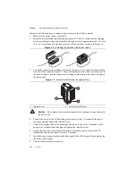
1.
Fasten the mounting plate to the controller using a number 2 Phillips screwdriver and
M4 × 10 screws
1
. National Instruments provides these screws with the panel mount kit.
Tighten the screws to a maximum torque of 1.3 N ·
m (11.5 lb ·
in.).
NI 9263
NI 9263
NI 9263
NI 9263
25.4 mm (1.00 in.)
Cooling Dimen
s
ion
s
50.
8
mm (2.00 in.)
C
ab
ling Cle
a
r
a
nce
25.4 mm (1.00 in.)
Cooling Dimen
s
ion
s
50.
8
mm (2.00 in.)
Me
asu
re Am
b
ient
Temper
a
t
u
re Here
27.
8
mm
(1.09 in.)
6
3
.5 mm
(2.50 in.)
6
3
.5 mm
(2.50 in.)
38
.1 mm
(1.50 in.)
38
.1 mm
(1.50 in.)
Me
asu
re Am
b
ient
Temper
a
t
u
re Here
NI cD
A
Q
-9135
NI CompactD
A
Q
USER1
SD
PUSH T
O
EJECT
NI 9263
NI 9263
NI 9263
NI 9263
25.4 mm (1.00 in.)
Cooling Dimen
s
ion
s
25.4 mm (1.00 in.)
Cooling Dimen
s
ion
s
50.
8
mm (2.00 in.)
27.
8
mm
(1.09 in.)
6
3
.5 mm
(2.50 in.)
38
.1 mm
(1.50 in.)
NI cD
A
Q
-9135
NI CompactD
A
Q


