1-30
|
ni.com
Chapter 1
Getting Started with the cDAQ Controller
Figures 1-22 and 1-23 show the dimensions of the 4-slot and 8-slot cDAQ controllers with
installed Module Immobilization accessory.
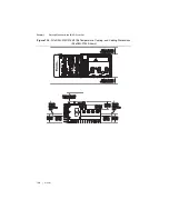
Figure 1-22.
Dimensions of the cDAQ-9132/9134/9136 with Module Immobilization
Accessory Installed
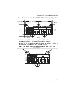
Figure 1-23.
Dimensions of the cDAQ-9133/9135/9137 with Module Immobilization
Accessory Installed
cDAQ Controller Features
The cDAQ controller features many ports, LEDs, a RESET button, a power button, and an
SD card slot. Refer to Figure 1-1 or 1-2 for the locations of these features on the cDAQ
controller.
Mini DisplayPort Connector
Use the mini DisplayPort connector, shown in Figure 1-1 or 1-2, to connect a monitor to
program Windows cDAQ controllers or implement a local HMI for Real-Time cDAQ
controllers. You can use a single real-time VI to iteratively develop both your user interface and
system logic. For more information, refer to the
Using the Embedded UI to Access RT Target
VIs
topic in the
LabVIEW Help
.
NI cD
A
Q
-9134
N
I c
D
A
Q
-9
13
4
NI CompactDAQN
I C
om
pa
ct
D
A
Q
200.
38
mm
(
8
.676 in.)
94.19 mm
(
3
.70
8
in.)
1.5
8
mm
(0.062 in.)
3
29.7
3
mm
(12.9
8
1 in.)
94.19 mm
(
3
.70
8
in.)
1.5
8
mm
(.062 in.)
NI 9263
NI 9263
NI 9263
NI 9263
NI 9263
NI 9263
NI 9263
NI 9263

