4-12
|
ni.com
Chapter 4
Digital Input/Output and PFI
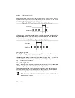
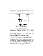
When you generate digital output signals, the generation pauses as soon as the pause trigger is
asserted. If the source of the sample clock is the onboard clock, the generation resumes as soon
as the pause trigger is deasserted, as shown in Figure 4-5.
Figure 4-5.
DO Pause Trigger with the Onboard Clock Source
If you are using any signal other than the onboard clock as the source of the sample clock, the
generation resumes as soon as the pause trigger is deasserted and another edge of the sample
clock is received, as shown in Figure 4-6.
Figure 4-6.
DO Pause Trigger with Other Signal Source
Using a Digital Source
To use DO Pause Trigger, specify a source and a polarity. The source can be a PFI signal or one
of several other internal signals on the cDAQ controller.
You also can specify whether the samples are paused when DO Pause Trigger is at a logic high
or low level. Refer to the
Device Routing in MAX
topic in the
NI-DAQmx Help
or the
LabVIEW Help
for more information.
Using an Analog Source
Some C Series modules can generate a trigger based on an analog signal. In NI-DAQmx, this is
called the Analog Comparison Event, depending on the trigger properties.
When you use an analog trigger source, the samples are paused when the Analog Comparison
Event signal is at a high or low level, depending on the trigger properties. The analog trigger
circuit must be configured by a simultaneously running analog input task.
Note
Depending on the C Series module capabilities, you may need two modules
to utilize analog triggering.
Pause Trigger
Sample Clock
Pause Trigger
Sample Clock


