


+
–
+
–
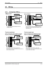
FP0 Hardware
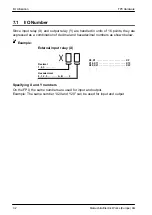
5.3
Specifications
5-7
Matsushita Electric Works (Europe) AG
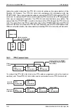
Cable
Cross–section
Twisted pair
with shield
shield
conductor
jacket
insulator
VCTF
molding
jacket
insulator
conductor
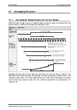
Notes
1) The electric characteristic of polyvinyl chloride is inferior to
polyethylene, so the maximum communication distance is
short.
2) Twisted pair cable should be a shielded type.
3) Use only one type of communication cable, i.e. do not mix
cable types.
4) Twisted pair cable should especially be used in an
environment with extensive noise.
5) If AFP3740, AFP87441, AFP87442, AFP3741 are in the network,
the communication distance should be limited as stated
above.
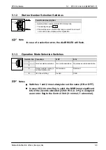
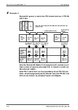
5.3.5
Terminal Pin Layout
Each
and
terminal is connected internally. The ground terminal is
connected internally to the power supply’s top pin on the side of the unit.
Using relayed wiring, the ingoing cable should be connected to the upper
terminal and the outgoing cable should be connected from the lower
terminal (
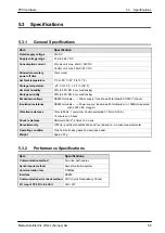
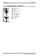
5.3.6
Communication Line Wiring Diagram
FG
FG
I/O Link Unit
Slave station
Slave station
(Shield)
(Shield)
(Shield)
Communication
cable
Communication
cable
Communication
cable
Содержание FP Series
Страница 12: ...Chapter 1 Overview...
Страница 21: ...FP0 Hardware Overview 1 10 Matsushita Electric Works Europe AG...
Страница 22: ...Chapter 2 Control Units...
Страница 44: ...Chapter 3 Expansion I O Units...
Страница 67: ...FP0 Hardware Expansion I O Units 3 24 Matsushita Electric Works Europe AG...
Страница 68: ...Chapter 4 Analog I O Unit...
Страница 87: ...FP0 Hardware Analog I O Unit 4 20 Matsushita Electric Works Europe AG...
Страница 88: ...Chapter 5 FP0 I O Link Unit MEWNET F...
Страница 102: ...Chapter 6 Power Supply Unit...
Страница 105: ...FP0 Hardware Power Supply Unit 6 4 Matsushita Electric Works Europe AG...
Страница 106: ...Chapter 7 I O Allocation...
Страница 112: ...Chapter 8 Installation...
Страница 122: ...Chapter 9 Wiring...
Страница 139: ...FP0 Hardware Wiring 9 18 Matsushita Electric Works Europe AG...
Страница 140: ...Chapter 10 Trial Operation...
Страница 143: ...FP0 Hardware Trial Operation 10 4 Matsushita Electric Works Europe AG...
Страница 144: ...Chapter 11 Self Diagnostic and Troubleshooting...
Страница 156: ...Appendix A System Registers...
Страница 170: ...Appendix B Special Internal Relays...
Страница 174: ...Appendix C Special Data Registers...
Страница 183: ...FP0 Hardware Special Data Registers C 10 Matsushita Electric Works Europe AG...
Страница 184: ...Appendix D Dimensions...
Страница 195: ...FP0 Hardware Dimensions D 12 Matsushita Electric Works Europe AG...