


FP0 Hardware
System Registers
A-2
Matsushita Electric Works (Europe) AG
A.1
System Registers
System registers are used to set values (parameters) which determine operation
ranges and functions used. Set values based on the use and specifications of your
program.
There is no need to set system registers for functions which will not be used.
The explanations in this chapter often utilize NPST–GR conventions. When using
FPWIN Pro for programming, please note these slight differences:
Hexadecimal values are represented by the prefix 16# and not H.
Decimal values do not require a K prefix.
Moreover in FPWIN Pro, there is an “Additional Information” column for each System
Register that briefly explains its use.
A.1.1
Types of System Registers
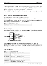
Allocation of timers and counters (System register 5)
The number of timers and counters is set by specifying the leading counter number.
Hold types and non–hold type settings (System register 6 to 8 and 14)
With the FP0, the areas held in the event of a power supply interruption are fixed, and
the settings for system register 6 to 8 and 14, will be invalid.
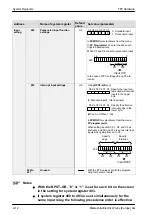
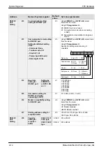
Operation mode settings for errors (System register 20, 23 ,26 and 27)
Set the operation mode effective when errors such as duplicated use of output,
operation, and I/O verification errors occur.
Time settings (System register 31 and 34)
Set the time–out error detection time and the constant scan time.
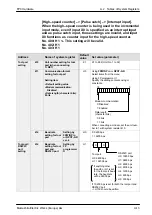
Input settings (System register 400 to 403)
When using the high–speed counter function, pulse catch function or interrupt function,
set the operation mode and the input number to be used as a special input.
Tool port settings (System register 410, 411 and 414)
Set the tool port parameters when computer link will be used.
RS232C port settings (System register 412 to 418)
Only applicable for unit with RS232C port.
Modem connection setting (System register 411)
Set to ”Modem connection” when the tool port will be used for modem communication.
A.1.2
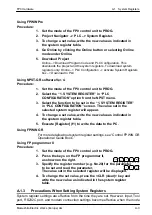
Checking and Changing System Register Settings
System register values (parameters) can be set with decimal or hexadecimal constants.
If you are going to use a value which is already set (the value which appears when read),
there is no need to write it again.
Содержание FP Series
Страница 12: ...Chapter 1 Overview...
Страница 21: ...FP0 Hardware Overview 1 10 Matsushita Electric Works Europe AG...
Страница 22: ...Chapter 2 Control Units...
Страница 44: ...Chapter 3 Expansion I O Units...
Страница 67: ...FP0 Hardware Expansion I O Units 3 24 Matsushita Electric Works Europe AG...
Страница 68: ...Chapter 4 Analog I O Unit...
Страница 87: ...FP0 Hardware Analog I O Unit 4 20 Matsushita Electric Works Europe AG...
Страница 88: ...Chapter 5 FP0 I O Link Unit MEWNET F...
Страница 102: ...Chapter 6 Power Supply Unit...
Страница 105: ...FP0 Hardware Power Supply Unit 6 4 Matsushita Electric Works Europe AG...
Страница 106: ...Chapter 7 I O Allocation...
Страница 112: ...Chapter 8 Installation...
Страница 122: ...Chapter 9 Wiring...
Страница 139: ...FP0 Hardware Wiring 9 18 Matsushita Electric Works Europe AG...
Страница 140: ...Chapter 10 Trial Operation...
Страница 143: ...FP0 Hardware Trial Operation 10 4 Matsushita Electric Works Europe AG...
Страница 144: ...Chapter 11 Self Diagnostic and Troubleshooting...
Страница 156: ...Appendix A System Registers...
Страница 170: ...Appendix B Special Internal Relays...
Страница 174: ...Appendix C Special Data Registers...
Страница 183: ...FP0 Hardware Special Data Registers C 10 Matsushita Electric Works Europe AG...
Страница 184: ...Appendix D Dimensions...
Страница 195: ...FP0 Hardware Dimensions D 12 Matsushita Electric Works Europe AG...