


FP0 Hardware
4.2
Specifications
4-7
Matsushita Electric Works (Europe) AG
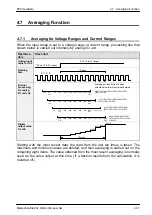
5) Refer to the schematic diagram of insulation methods below.
FP0
Control
unit
I/F
P h o t o c o u p l e r
insulation
Analog input
Analog output
Analog I/O unit
DC/DC converter
insulation
CH0
24V DC
+5V
Bus
CH1
DC/DC converter
insulation
P h o t o c o u p l e r
insulation
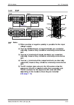
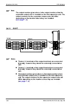
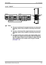
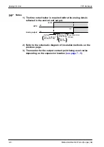
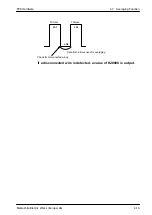
6) The number for the input contact point being used varies
depending on the expansion location (
4.2.3
Analog Output Specifications
Item
Description
Number of output points
ÁÁÁÁÁÁÁÁÁÁÁÁÁÁÁÁÁÁ
ÁÁÁÁÁÁÁÁÁÁÁÁÁÁÁÁÁÁ
1 channel/unit
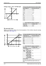
Output range
Voltage range
ÁÁÁÁÁÁÁÁÁÁÁÁÁÁÁÁÁÁ
ÁÁÁÁÁÁÁÁÁÁÁÁÁÁÁÁÁÁ
–10 to +10V
Current range
ÁÁÁÁÁÁÁÁÁÁÁÁÁÁÁÁÁÁ
ÁÁÁÁÁÁÁÁÁÁÁÁÁÁÁÁÁÁ
0 to 20mA
Digital input
–10 to +10V
ÁÁÁÁÁÁÁÁÁÁÁÁÁÁÁÁÁÁ
K – 2000 to K + 2000 (HF830 to H07D0)
0 to 20mA
ÁÁÁÁÁÁÁÁÁÁÁÁÁÁÁÁÁÁ
ÁÁÁÁÁÁÁÁÁÁÁÁÁÁÁÁÁÁ
K0 to K4000 (H0 to H0FA0)
Resolution
ÁÁÁÁÁÁÁÁÁÁÁÁÁÁÁÁÁÁ
ÁÁÁÁÁÁÁÁÁÁÁÁÁÁÁÁÁÁ
1/4000
Conversion speed
ÁÁÁÁÁÁÁÁÁÁÁÁÁÁÁÁÁÁ
ÁÁÁÁÁÁÁÁÁÁÁÁÁÁÁÁÁÁ
500
µ
s (
see note 1
)
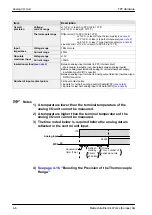
Overall precision
ÁÁÁÁÁÁÁÁÁÁÁÁÁÁÁÁÁÁ
ÁÁÁÁÁÁÁÁÁÁÁÁÁÁÁÁÁÁ
ÁÁÁÁÁÁÁÁÁÁÁÁÁÁÁÁÁÁ
±
1% F.S. or less (0 to 55
°
C/32 to 131
°
F)
±
0.6% F.S. or less (25
°
C/77
°
F)
Output impedence
Voltage range
ÁÁÁÁÁÁÁÁÁÁÁÁÁÁÁÁÁÁ
0.5
Ω
Maximum output
current
Voltage range
ÁÁÁÁÁÁÁÁÁÁÁÁÁÁÁÁÁÁ
ÁÁÁÁÁÁÁÁÁÁÁÁÁÁÁÁÁÁ
ÁÁÁÁÁÁÁÁÁÁÁÁÁÁÁÁÁÁ
±
10mA
Allowable output
load resistance
Current range
ÁÁÁÁÁÁÁÁÁÁÁÁÁÁÁÁÁÁ
ÁÁÁÁÁÁÁÁÁÁÁÁÁÁÁÁÁÁ
300
Ω
or less
Insulation method (
see note 2
)
ÁÁÁÁÁÁÁÁÁÁÁÁÁÁÁÁÁÁ
ÁÁÁÁÁÁÁÁÁÁÁÁÁÁÁÁÁÁ
ÁÁÁÁÁÁÁÁÁÁÁÁÁÁÁÁÁÁ
ÁÁÁÁÁÁÁÁÁÁÁÁÁÁÁÁÁÁ
ÁÁÁÁÁÁÁÁÁÁÁÁÁÁÁÁÁÁ
Between analog output terminal to FP0 internal circuit:
Photocoupler insulation
Between analog output terminal to analog I/O unit external power supply:
insulation-type DC/DC converter
Between analog output terminal to analog input terminal:
insulation-type DC/DC converter
Number of output contact points
ÁÁÁÁÁÁÁÁÁÁÁÁÁÁÁÁÁÁ
ÁÁÁÁÁÁÁÁÁÁÁÁÁÁÁÁÁÁ
16 output contact points: analog output data (WY2) (
see note 3
)
Содержание FP Series
Страница 12: ...Chapter 1 Overview...
Страница 21: ...FP0 Hardware Overview 1 10 Matsushita Electric Works Europe AG...
Страница 22: ...Chapter 2 Control Units...
Страница 44: ...Chapter 3 Expansion I O Units...
Страница 67: ...FP0 Hardware Expansion I O Units 3 24 Matsushita Electric Works Europe AG...
Страница 68: ...Chapter 4 Analog I O Unit...
Страница 87: ...FP0 Hardware Analog I O Unit 4 20 Matsushita Electric Works Europe AG...
Страница 88: ...Chapter 5 FP0 I O Link Unit MEWNET F...
Страница 102: ...Chapter 6 Power Supply Unit...
Страница 105: ...FP0 Hardware Power Supply Unit 6 4 Matsushita Electric Works Europe AG...
Страница 106: ...Chapter 7 I O Allocation...
Страница 112: ...Chapter 8 Installation...
Страница 122: ...Chapter 9 Wiring...
Страница 139: ...FP0 Hardware Wiring 9 18 Matsushita Electric Works Europe AG...
Страница 140: ...Chapter 10 Trial Operation...
Страница 143: ...FP0 Hardware Trial Operation 10 4 Matsushita Electric Works Europe AG...
Страница 144: ...Chapter 11 Self Diagnostic and Troubleshooting...
Страница 156: ...Appendix A System Registers...
Страница 170: ...Appendix B Special Internal Relays...
Страница 174: ...Appendix C Special Data Registers...
Страница 183: ...FP0 Hardware Special Data Registers C 10 Matsushita Electric Works Europe AG...
Страница 184: ...Appendix D Dimensions...
Страница 195: ...FP0 Hardware Dimensions D 12 Matsushita Electric Works Europe AG...


