


FP0 Hardware
Special Data Registers
C-4
Matsushita Electric Works (Europe) AG
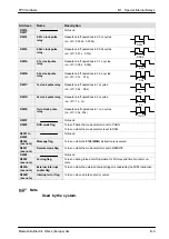
Notes
1) Scan time display is only possible in RUN mode, and shows
the operation cycle time. The maximum and minimum values
are cleared when each the mode is switched between RUN
mode and PROG. mode.
2) Used by the system.
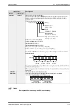
Addresses
Description
T32CP
Other Types
DT90038
DT9038
Work 2 for F96 (SRC) instruction
The position of the first matching data, counting from the starting 16-bit area, is
stored here when an F96 (SRC) instruction is executed.
DT90039 to
DT90043
DT9039 to
DT9043
Not used
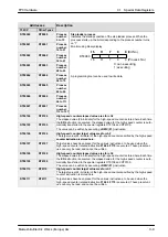
DT90044
DT9044
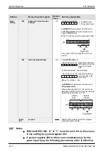
High-speed counter elapsed value for ch0
The elapsed value (24–bit data) for the high–speed counter is stored here. Each time
DT90045
DT9045
the ED instruction is executed, the elapsed value for the high–speed counter is auto-
matically transferred to the special registers DT9044 and DT9045.
The value can be written by executing a DMV (F1) instruction.
DT90046
DT9046
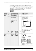
High-speed counter target value for ch0
The target value (24–bit data) of the high–speed counter specified by the high–speed
counter instruction is stored here.
DT90047
DT9047
counter instruction is stored here.
Target values have been preset for the various instructions, to be used when the
high–speed counter related instruction F166 to F170 is executed. These preset val-
ues can only be read, and cannot be written.
DT90048
DT9048
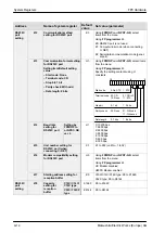
High-speed counter elapsed value area for ch1
The elapsed value (24–bit data) for the high–speed counter is stored here. Each time
DT90049
DT9049
the ED instruction is executed, the elapsed value for the high–speed counter is auto-
matically transferred to the special registers DT9048 and DT9049.
The value can be written by executing a DMV (F1) instruction.
DT90050
DT9050
High-speed counter target value area for ch1
The target value (24–bit data) of the high–speed counter specified by the high–speed
counter instruction is stored here.
DT90051
DT9051
counter instruction is stored here.
Target values have been preset for the various instructions, to be used when the
high–speed counter related instruction F166 to F170 is executed. These preset val-
ues can only be read, and cannot be written.
Содержание FP Series
Страница 12: ...Chapter 1 Overview...
Страница 21: ...FP0 Hardware Overview 1 10 Matsushita Electric Works Europe AG...
Страница 22: ...Chapter 2 Control Units...
Страница 44: ...Chapter 3 Expansion I O Units...
Страница 67: ...FP0 Hardware Expansion I O Units 3 24 Matsushita Electric Works Europe AG...
Страница 68: ...Chapter 4 Analog I O Unit...
Страница 87: ...FP0 Hardware Analog I O Unit 4 20 Matsushita Electric Works Europe AG...
Страница 88: ...Chapter 5 FP0 I O Link Unit MEWNET F...
Страница 102: ...Chapter 6 Power Supply Unit...
Страница 105: ...FP0 Hardware Power Supply Unit 6 4 Matsushita Electric Works Europe AG...
Страница 106: ...Chapter 7 I O Allocation...
Страница 112: ...Chapter 8 Installation...
Страница 122: ...Chapter 9 Wiring...
Страница 139: ...FP0 Hardware Wiring 9 18 Matsushita Electric Works Europe AG...
Страница 140: ...Chapter 10 Trial Operation...
Страница 143: ...FP0 Hardware Trial Operation 10 4 Matsushita Electric Works Europe AG...
Страница 144: ...Chapter 11 Self Diagnostic and Troubleshooting...
Страница 156: ...Appendix A System Registers...
Страница 170: ...Appendix B Special Internal Relays...
Страница 174: ...Appendix C Special Data Registers...
Страница 183: ...FP0 Hardware Special Data Registers C 10 Matsushita Electric Works Europe AG...
Страница 184: ...Appendix D Dimensions...
Страница 195: ...FP0 Hardware Dimensions D 12 Matsushita Electric Works Europe AG...


