


FP0 Hardware
C.1 Special Data Registers
C-9
Matsushita Electric Works (Europe) AG
Addresses
Description
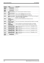
T32CP
Other Types
DT90060
DT9060
Process
number:
0 to 15
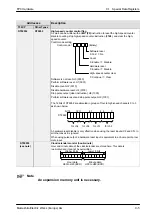
Step ladder process
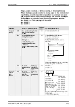
Indicates the startup condition of the step ladder process. When the
proccess starts up, the bit corresponding to the process number turns
DT90061
DT9061
Process
number:
16 to 31
15
11
7
3
0
on “1”.
Monitor using binary display.
DT90062
DT9062
Process
number:
32 to 47
DT9060
15
11
7
3
0
(Bit No.)
15
11
7
3
0
(Process No.)
DT90063
DT9063
Process
number:
48 to 63
0: not–executing
1: executing
DT90064
DT9064
Process
number:
64 to 79
A programming tool can be used to write data.
DT90065
DT9065
Process
number:
80 to 95
DT90066
DT9066
Process
number:
96 to 111
DT90067
DT9067
Process
number:
112 to 127
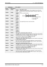
DT90104
DT9104
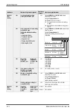
High-speed counter elapsed value area for ch2
The elapsed value (24–bit data) for the high–speed counter is stored here. Each time
DT90105
DT9105
the ED instruction is executed, the elapsed value for the high–speed counter is auto-
matically transferred to the special registers DT9104 and DT9105.
The value can be written by executing a DMV (F1) instruction.
DT90106
DT9106
High-speed counter target value area for ch2
The target value (24–bit data) of the high–speed counter specified by the high–speed
counter instruction is stored here.
DT90107
DT9107
counter instruction is stored here.
Target values have been preset for the various instructions, to be used when the
high–speed counter related instruction F166 to F170 is executed. These preset val-
ues can only be read, and cannot be written.
DT90108
DT9108
High-speed counter elapsed value area for ch3
The elapsed value (24–bit data) for the high–speed counter is stored here. Each time
DT90109
DT9109
the ED instruction is executed, the elapsed value for the high–speed counter is auto-
matically transferred to the special registers DT9108 and DT9109.
The value can be written by executing a DMV (F1) instruction.
DT90110
DT9110
High-speed counter target value area for ch3
The target value (24–bit data) of the high–speed counter specified by the high–speed
counter instruction is stored here.
DT90111
DT9111
counter instruction is stored here.
Target values have been preset for the various instructions, to be used when the
high–speed counter related instruction F166 to F170 is executed. These preset val-
ues can only be read, and cannot be written.
Содержание FP Series
Страница 12: ...Chapter 1 Overview...
Страница 21: ...FP0 Hardware Overview 1 10 Matsushita Electric Works Europe AG...
Страница 22: ...Chapter 2 Control Units...
Страница 44: ...Chapter 3 Expansion I O Units...
Страница 67: ...FP0 Hardware Expansion I O Units 3 24 Matsushita Electric Works Europe AG...
Страница 68: ...Chapter 4 Analog I O Unit...
Страница 87: ...FP0 Hardware Analog I O Unit 4 20 Matsushita Electric Works Europe AG...
Страница 88: ...Chapter 5 FP0 I O Link Unit MEWNET F...
Страница 102: ...Chapter 6 Power Supply Unit...
Страница 105: ...FP0 Hardware Power Supply Unit 6 4 Matsushita Electric Works Europe AG...
Страница 106: ...Chapter 7 I O Allocation...
Страница 112: ...Chapter 8 Installation...
Страница 122: ...Chapter 9 Wiring...
Страница 139: ...FP0 Hardware Wiring 9 18 Matsushita Electric Works Europe AG...
Страница 140: ...Chapter 10 Trial Operation...
Страница 143: ...FP0 Hardware Trial Operation 10 4 Matsushita Electric Works Europe AG...
Страница 144: ...Chapter 11 Self Diagnostic and Troubleshooting...
Страница 156: ...Appendix A System Registers...
Страница 170: ...Appendix B Special Internal Relays...
Страница 174: ...Appendix C Special Data Registers...
Страница 183: ...FP0 Hardware Special Data Registers C 10 Matsushita Electric Works Europe AG...
Страница 184: ...Appendix D Dimensions...
Страница 195: ...FP0 Hardware Dimensions D 12 Matsushita Electric Works Europe AG...


