


FP0 Hardware
Wiring
9-8
Matsushita Electric Works (Europe) AG
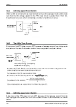
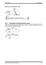
9.4.2
LED-Equipped Reed Switch
When a LED is connected to an input contact such as LED-equipped reed switch, make
sure that the ON voltage applied to the FP0 input circuit is greater than 19.2V DC.
In particular, take care when connecting a number of switches in series.
FP0
19.2V DC
or more
24V DC
LED-equipped
reed switch
COM
Input
terminal
9.4.3
Two-Wire Type Sensor
If the input of the FP0 does not turn OFF because of leakage current from the two-wire
type sensor, the use of a bleeder resistor is recommended, as shown below.
The OFF voltage of the FP0 input is 2.4V, therefore, select an R value so that the voltage between the
COM terminal and the input terminal will be less than 2.4V.
The impedance of the FP0 input terminal is 5.6k
Ω
.
The resistance R of the bleeder resistor is: R
≤
The wattage W of the resistor is:
In the actual selection, use a value that is 3 to 5 times the value of W.
13.44
(k
Ω
)
Two-wire
type sensor
FP0
5.6
×
I
– 2.4
COM
Input terminal
Internal
circuit
Bleeder
resistor
I: Sensor’s leakage current (mA)
R: Bleeder resistor (k
W
)
(Power supply voltage)
2
R
W
=
9.4.4
LED-Equipped Limit Switch
If the input of the FP0 does not turn OFF because of the leakage current from the
LED-equipped limit switch, the use of a bleeder resistor is recommended, as shown
below.
Содержание FP Series
Страница 12: ...Chapter 1 Overview...
Страница 21: ...FP0 Hardware Overview 1 10 Matsushita Electric Works Europe AG...
Страница 22: ...Chapter 2 Control Units...
Страница 44: ...Chapter 3 Expansion I O Units...
Страница 67: ...FP0 Hardware Expansion I O Units 3 24 Matsushita Electric Works Europe AG...
Страница 68: ...Chapter 4 Analog I O Unit...
Страница 87: ...FP0 Hardware Analog I O Unit 4 20 Matsushita Electric Works Europe AG...
Страница 88: ...Chapter 5 FP0 I O Link Unit MEWNET F...
Страница 102: ...Chapter 6 Power Supply Unit...
Страница 105: ...FP0 Hardware Power Supply Unit 6 4 Matsushita Electric Works Europe AG...
Страница 106: ...Chapter 7 I O Allocation...
Страница 112: ...Chapter 8 Installation...
Страница 122: ...Chapter 9 Wiring...
Страница 139: ...FP0 Hardware Wiring 9 18 Matsushita Electric Works Europe AG...
Страница 140: ...Chapter 10 Trial Operation...
Страница 143: ...FP0 Hardware Trial Operation 10 4 Matsushita Electric Works Europe AG...
Страница 144: ...Chapter 11 Self Diagnostic and Troubleshooting...
Страница 156: ...Appendix A System Registers...
Страница 170: ...Appendix B Special Internal Relays...
Страница 174: ...Appendix C Special Data Registers...
Страница 183: ...FP0 Hardware Special Data Registers C 10 Matsushita Electric Works Europe AG...
Страница 184: ...Appendix D Dimensions...
Страница 195: ...FP0 Hardware Dimensions D 12 Matsushita Electric Works Europe AG...


