Rev. 10-7-16
Part #C-00140
GT20 Control Wiring and Programming Manual
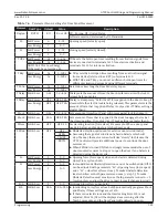
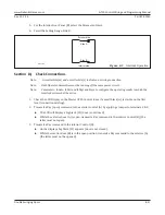
Relay Print
9-39
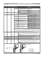
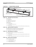
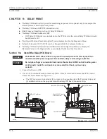
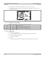
3.►Insert (4) M3 x 12 Stand Off Torx Screws within each screw hole.
4.►Secure the Relay PCB Board onto the GT20 Control with (4) M3 x 5 Torx Screws.
5.►Proceed to wire each PCB Terminal accordingly.
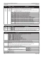
Section 9b: Program the Relay PCB Board
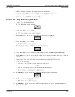
1.►Switch-on the Main Power Switch.
a. The Home Page will be displayed.
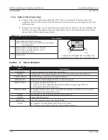
>##<
E01
2.►Briefly push down on the Joystick.
a. The Menu Selection Page will be displayed.
3.►Move the Joystick to the Right or Left until the Menu CONFIG is displayed.
CONFIG
4.►Briefly push down on the Joystick.
a. An Element Page will be displayed.
5.►Move the Joystick Down until the Element RC 0.1 is displayed.
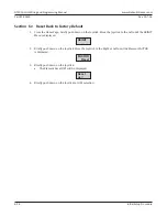
RC 0.1
CLOSED
6.►Briefly push down on the Joystick. The Value will start to blink on the lower half of the screen.
7.►Move the Joystick to the Right or to the Left to select(1) the appropriate Value. For details, please see
8.►Repeat steps 5 thru 7 until all Relay PCBs are programmed within the GT20 Control.
9.►Go back to the Menu Page:
1.►Push down on the Joystick until the Menu Page is displayed.
OR
1.►Move the Joystick Up or Down until the Element ESC is displayed.
2.►Briefly push down on the Joystick to (OK) selection.
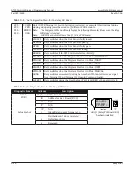
10.►Move the Joystick to the Right or Left until the Menu DIAGNOSTICS is displayed.
DIAGNO-
STICS
11.►Briefly push down on the Joystick.
a. The Element Page will be displayed.
12.►Move the Joystick to the Right or Left until the Element RO+ R1- FP- RP- is displayed. For details
Содержание GT20
Страница 2: ...THIS PAGE IS INTENTIONALLY LEFT BLANK...


