GT20 Control Wiring and Programming Manual
Part #C-00140
Rev. 10-7-16
9-38
Relay Print
CHAPTER 9: RELAY PRINT
X
The Relay PCB Board is strictly used for monitoring purposes and is optional only. For example: Fire
Alarm Systems, or Security Alarm Systems.
X
The Relay PCB Board OUTPUTS information only.
X
NABCO does not install more than (1) Relay PCB Board.
X
The Relay PCB Board Address is (R0).
•
If (2) Relay PCB Boards were installed onto the GT20 Control the second Relay PCB Board would
be addressed as R1.
X
The status of the Door Panel during Real Time is displayed within the Diagnostic Menu.
X
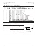
Values for Elements (RC 01...RC 04) can be changed within the Configuration Menu.
X
The Relay PCB Board (RO) must be installed before the Configuration Menu can display the
Elements/Values or the Diagnostic Menu can display the Status of the Door Panel.
Section 9a: Install the Relay PCB Board.
Shut Breaker OFF. Failure to do so may result in serious personal or fatal injury. When
uncertain whether power supply is disconnected, always verify using a voltmeter.
Do not place finger or uninsulated tools inside the electrical GT20 Control. Touching wires
or other parts inside the enclosure may cause electrical shock, serious injury
or death .
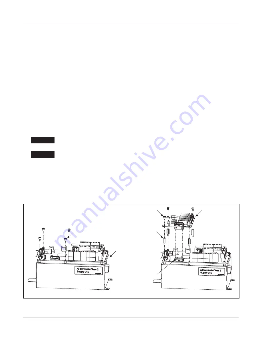
1.►Ensure the Power is OFF.
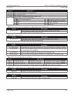
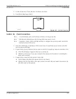
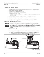
2.►Use a T-10 Torx Allen Wrench to remove (4) M3 x 5 Torx Screws used to secure the GT20 Control
Board. Set Aside. Please see Figure 9-1.
a. The (4) Torx screws are located at (2) corners on the opposite side of the Terminal Strips and
(2) middle location on the opposite side of the Relay PCB Board Connector Strip.
DN 1264
Female Connector
GT20 Control
Relay PCB Board
(4x) M3 x 12 Stand
Off Torx Screw
(4x) M3 x 5 Torx Screw
M3 x 5 Torx Screw
Figure 9-1
Relay PCB
DANGER
DANGER
Содержание GT20
Страница 2: ...THIS PAGE IS INTENTIONALLY LEFT BLANK...