101
Appendix 4.10
Networking
Up to sixty three MA-1000 panels can be networked together to operate as a single networked
system. To achieve this each panel must be fitted with a network card.
When operating as a networked system all fire and fault information is displayed at every panel,
silencing and resetting of alarms can also be carried out from any panel on a networked system if
panels are suitably configured.
Networked panels are connected using a loop topology as illustrated below.
Screen continuity must be maintained throughout the entire network circuit including at each
junction point. The screen should only be earthed at the connection point provided at the first panel
and not at any other point. The screen or drain wire of the network cable should not be considered
as a safety earth and therefore should not be connected to terminals marked with the earth symbol,
except at the panel, and should not be insulated with green and yellow sleeving
Where the network cable passes between buildings, screen continuity should not be maintained
from building to building. A booster device must however be used irrespective of cable length and
should be fitted at a suitable point in the link between buildings. The cable screen should be
connected to the earth of one panel in each building.
The PC Software enables the address, location text, device type and any comments to be
downloaded to the MA-1000 panels.
The software can download to all 63 networkable Panels.
The PC is connected to each Panel on the network in turn. All data for the Panel is downloaded.
For networked systems, panels are identified by panel number, P1, P2 etc.
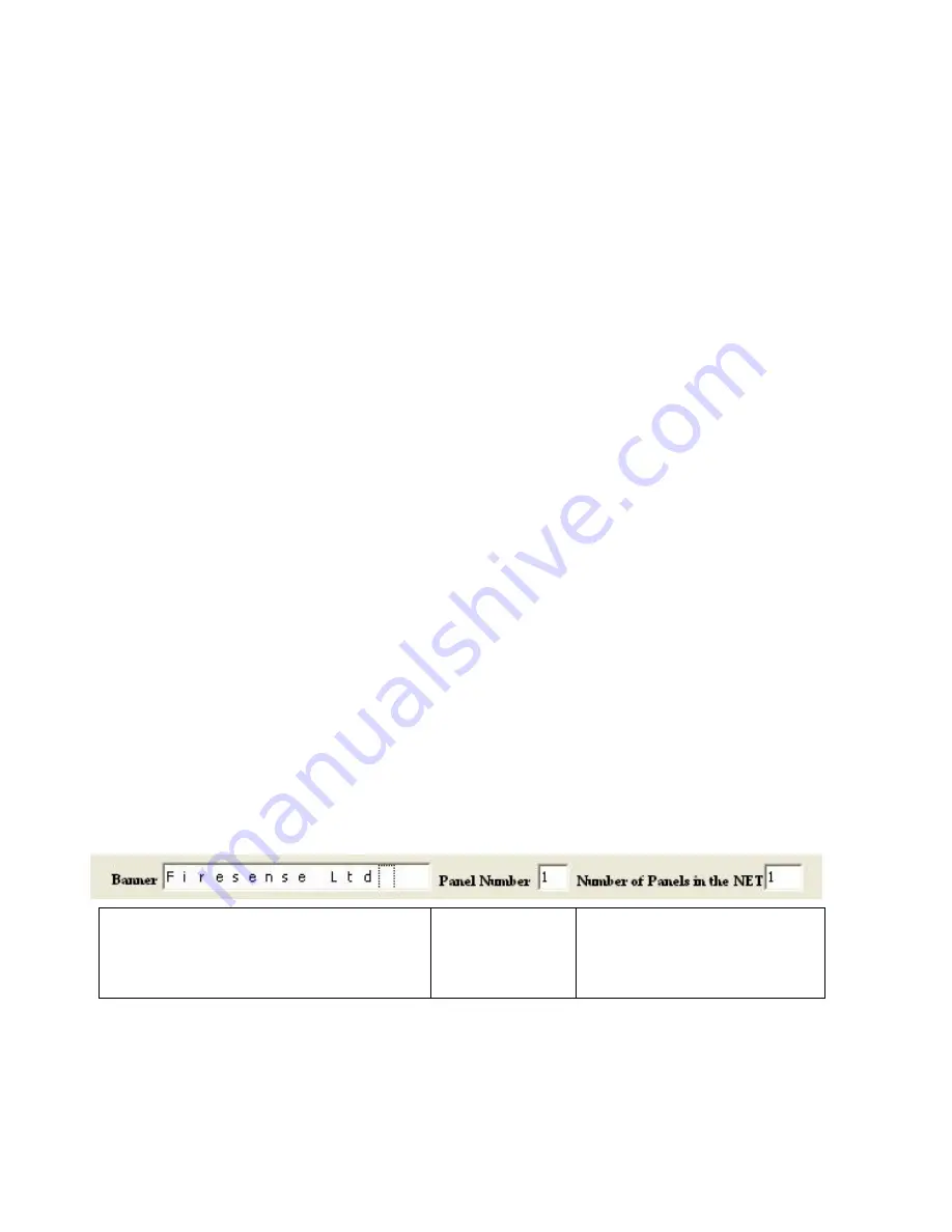
NETWORK SETUP
1. From PC program set panel id number.
2. Set number of panels in the network (amount of panels)
Panel Name
Set Panel
Number (The
panel ID
number)
Set Number of Panels in the
Network ( The amount of
panels in the NETWORK)
Note: refer to Fig: 1 for wiring connections
Содержание MA-1000
Страница 2: ...1 ...
Страница 3: ...2 ...
Страница 15: ...14 MA 1000 ...
Страница 17: ...16 Peripheral Devices ...
Страница 62: ...61 Appendix 4 9 MA 1000 Site Installer User Manual ...
Страница 63: ...62 ...
Страница 71: ...70 ...
Страница 76: ...75 FIGURE 12 Allocated devices list ...
Страница 80: ...79 FIGURE 14 Allocated List ...
Страница 84: ...83 6 Select Delete Device button FIGURE 19 Select Device ...
Страница 88: ...87 Save as TXT format ...
Страница 89: ...88 Panel outputs Save as EXEL format ...
Страница 90: ...89 2 2 13 History Events 1 Select Read History button FIGURE 23 Read History FIGURE 23 Save Event list ...
Страница 91: ...90 FIGURE 21 View Event 2 History will display automatically in the default browser ...
Страница 93: ...92 4 Select Add panel or Delete panel 5 Select Close to apply ...
Страница 98: ...97 ...
Страница 103: ...102 Fig 1 ...
Страница 105: ...104 Appendix 4 12 Detectors UL Certifications ...
Страница 106: ...105 ...
Страница 107: ...107 ...


