T: +1-613-545-0466 F: +1-613-542-8029 www.mrel.com
63
8.4.1 Image Processing
Allows the operator to change the color of the video which includes the
Brightness
,
Contrast
,
Gamma and Exponential
/
Logarithmic
.
Within this example, the user will notice that the individual colors can be adjusted be double clicking on the slider in question.
Below the sliders, the buttons can invert (reverse) the individual colors.
The
Convert to B&W
(Black and White) can change the color image to a grey scale. The sliders above the button can change the intensity
of the individual colors. Once in
B&W
, the sliders below will be able to be changed as above.
The
Load
and
Save
buttons will load a previously saved
Image Processing file
(*.lut) while
Save
will generate a lut file from the current
settings.
The Reset All will return all of the setting to the default location.
8.4.2 Multi-Plane Calibration
This tab will allow the user to calibrate the video file.
The software needs to relate the number of pixels to a known distance. The
Introductory Edition
can not use a perspective calibration as
can the other versions of the software.
The Normal calibration can be performed within
Introductory
. A Normal calibration is able to measure items that move at right angles to
the camera view.
To add a calibration, click on
Add Normal
and another line item will appear on the screen. Throughout this software package a standard
convention will repeat. For example, on the calibration line on the right, there is an eye either open or closed. If the eye is open, the
object is visible on the screen. If the eye is closed, the object will not be shown on the screen.
The wrench to the right of the eye will open a configuration menu. In the calibration wrench menu, it is labeled as Calibration # Settings
where # is the number of the calibration. When the operator clicks on the screen, the reticle (cross hair) will move to the position
clicked. If the operator then clicks on
Set Point #1
, the first point of the calibration will be set. The second point can be selected in a
similar method. After the two points are selected, the user can enter the value between the two points selected and then select the units of
measurement of the number from the pull down menu. After the units are selected, the
Apply Scale >>
button
MUST
be clicked. This will
change the box beside the button to xx pixels/“units selected”.
The origin of the coordinate system can be set in a similar method. Point the reticle to point were the operator requests the coordinate
origin to be (0,0). This will be the reference point for all of the measurements.
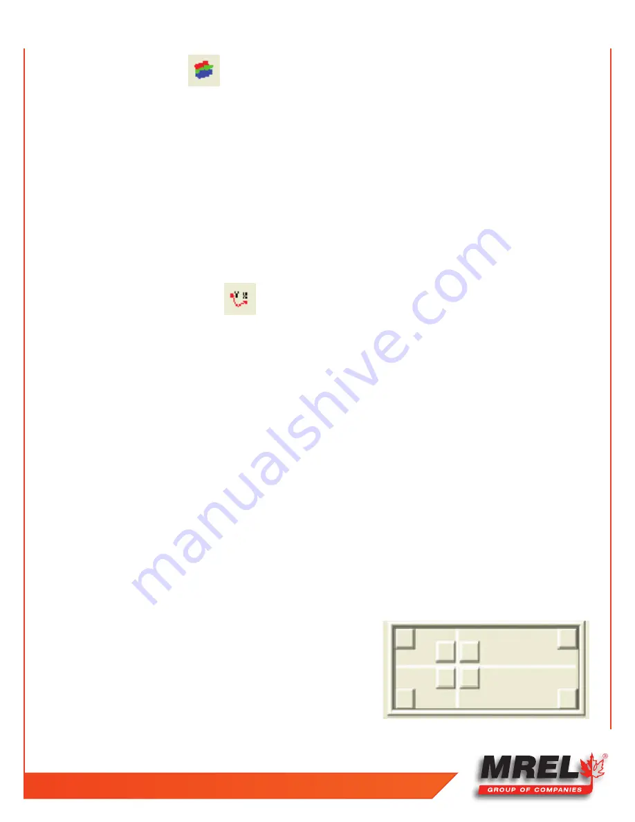
After the origin is set, the orientation of the axes must be set. As shown below,
each of the buttons in the picture will set the orientation of the axes.
Each of the corner buttons will set the origin of the coordinate system in the
respective corner. The positive orientation of the two axes will be along the edge
of the frame. For example, the top left button will set positive X direction to the
right and the positive Y direction down while the bottom right button will set the
Содержание Blaster's Ranger II Lt
Страница 7: ...T 1 613 545 0466 F 1 613 542 8029 www mrel com 1 Chapter 1 Introduction ...
Страница 10: ...4 Blaster s Ranger II Lt Operations Manual Edition 1 1 Lt ...
Страница 11: ...T 1 613 545 0466 F 1 613 542 8029 www mrel com 5 Chapter 2 Hardware ...
Страница 15: ...T 1 613 545 0466 F 1 613 542 8029 www mrel com 9 Chapter 3 Getting Started ...
Страница 19: ...T 1 613 545 0466 F 1 613 542 8029 www mrel com 13 Chapter 4 FasMotion ...
Страница 29: ...T 1 613 545 0466 F 1 613 542 8029 www mrel com 23 Chapter 5 Recording ...
Страница 47: ...T 1 613 545 0466 F 1 613 542 8029 www mrel com 41 Chapter 6 Using the Web App ...
Страница 55: ...T 1 613 545 0466 F 1 613 542 8029 www mrel com 49 Chapter 7 Field Operations ...
Страница 57: ...T 1 613 545 0466 F 1 613 542 8029 www mrel com 51 ...
Страница 61: ...T 1 613 545 0466 F 1 613 542 8029 www mrel com 55 Chapter 8 ProAnalyst Introductory Edition Software ...
Страница 74: ...68 Blaster s Ranger II Lt Operations Manual Edition 1 1 Lt ...
Страница 75: ...T 1 613 545 0466 F 1 613 542 8029 www mrel com 69 Chapter 9 Contacting MREL for Technical Support ...
Страница 77: ...T 1 613 545 0466 F 1 613 542 8029 www mrel com 71 ...


