Motortech VariStep3 Скачать руководство пользователя страница 56

8 Settings via the MICT 


56 

Rev. 08/2018 

8.9.2


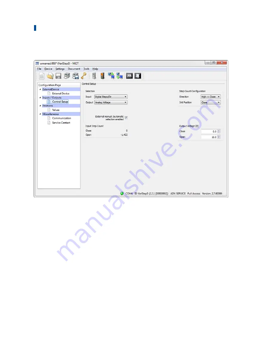
Inputs/Outputs – Control Setup 


The settings on the configuration page depend on the inputs and outputs used by your master 
control. In this case, refer to all information given in the relevant documentations of the control 
units. To make changes, approval for the access level 

Advanced Service

 is required. 

Selection 

– 

Input


Select the input that is to be used for position setting by the master control connected. The 
following options are possible: 

– 

Analog voltage


Position setting is achieved via the analog voltage signal. 

– 

Analog Current


Position setting is achieved via the analog current signal. 

– 

Digital Steps/Dir


Position setting is achieved via binary signals (

Steps

Dir

). 

– 

Field bus


Position setting is achieved via a field bus. This requires corresponding configuration of 
the communication with the desired field bus (see 

Miscellaneous – Communication

 on 

page 60). 

Содержание VariStep3

Страница 1: ...VariStep3 Stepper Motor Driver Operating Manual P N 01 50 020 EN Rev 08 2018...

Страница 2: ...are not permissible without express written approval by MOTORTECH Information contained in this publication may be changed without prior notice Trademarks MOTORTECH products and the MOTORTECH logo are...

Страница 3: ...3 3 1 Functional Description 13 3 2 Applications 13 4 Product Description 15 4 1 Technical Data 15 4 1 1 Certifications 15 4 1 2 Mechanical Data 17 4 1 3 Warning Notices on the Device 17 4 1 4 Product...

Страница 4: ...cess Control of the Stepper Motor Driver 47 8 7 1 Enable Disable Access Control 47 8 7 2 Login Logout 47 8 7 3 Changing the PIN 48 8 7 4 Reset all PINs 48 8 8 Working with Configurations 49 8 8 1 Crea...

Страница 5: ...Customer Service Information 79 10 5 Returning Equipment for Repair Inspection 80 10 6 Instructions for Packaging the Equipment 80 11 Maintenance 81 11 1 Spare Parts and Accessories 81 12 Annex 82 12...

Страница 6: ...level of technical knowledge with respect to the operation of gas engines and basic knowledge of electronic ignition systems are necessary Persons who are only authorized to operate the gas engine sh...

Страница 7: ...ne Conformity with EU directives Mark based on EU legislation for certain products in conjunction with product safety CPU Central Processing Unit Central processing unit DC Direct Current Direct curre...

Страница 8: ...warranties for the proper function of the equipment as well as the responsibility for the validity of the certifications Safety devices must not be dismounted or disabled Avoid all activities that ca...

Страница 9: ...rials Keep plastics such as vinyl and Styrofoam materials as far away from the control system the modules and the work environment as possible Do not remove the circuit boards from the housing of the...

Страница 10: ...s closed as a loop Due to impedance resistance R of the loop low frequency interference currents can lead to an unwanted voltage drop in the signal path Device 1 Device 2 Ground loop 2 4 Special Safet...

Страница 11: ...If the system is located in a hazardous area there is a risk of explosion Operational safety All screws of the connectors must be adequately tightened Risk of destruction due to electrostatic dischar...

Страница 12: ...ev 08 2018 2 5 Proper Disposal After the expiration of its service life MOTORTECH equipment can be disposed of with other commercial waste or it may be returned to MOTORTECH We will ensure its environ...

Страница 13: ...se provided by a master control are analyzed In addition a connection via CAN bus and Modbus is possible The stepper motor driver is configured using a connected PC The software used for this purpose...

Страница 14: ...v 08 2018 System Overview Example VariStep3 stepper motor drivers Engine VariFuel2 gas mixer Wiring rail ignition ITB throttle with integrated stepper motor Gas supply SC100 speed control Gas train Ai...

Страница 15: ...agnetic compatibility EMC Generic standards Immunity for industrial environments EN 61000 6 3 2007 A1 2011 Electromagnetic compatibility EMC Generic standards Emission standard for residential commerc...

Страница 16: ...4 Product Description 16 Rev 08 2018...

Страница 17: ...vice See chapter Overview Drawings on page 21 Mechanical environmental conditions Protection IP20 Climatic environmental conditions 20 C to 60 C 4 F to 140 F Max 85 humidity without condensation up to...

Страница 18: ...The numbers required for unique product identification are on the device Top of Device Abb Meaning P N Part number of the stepper motor driver S N Serial number of the stepper motor driver A N Arrang...

Страница 19: ...inputs and outputs of the stepper motor driver have the following electrical data Inputs and outputs Values characteristics Binary inputs Galvanically isolated Input voltage up to 32 V DC Input curren...

Страница 20: ...ference in potential relative to device ground 3 5 V Input resistance max 25 Analog voltage output Output voltage 0 V to 10 V Working resistance min 500 Analog current output Output current 0 mA to 20...

Страница 21: ...binary input is available for a reset signal see Wiring Binary Inputs on page 30 Binary Outputs Binary outputs which signal the position of the stepper motor and the status of the stepper motor driver...

Страница 22: ...s working properly Orange A warning occurred red An error occurred For additional information on warnings and errors read section Runtime Data Message Log on page 66 Manual Auto LED The LED lights up...

Страница 23: ...orange for the following reasons No device type has been configured device type None or Unknown Device connected was changed Overtemperature or over current error confirmed by MICT A reference run is...

Страница 24: ...truction due to electrostatic discharge The VariStep3 stepper motor driver may only be installed by specialized personnel who has been trained in handling ESD sensitive components and with due regard...

Страница 25: ...0 m 32 If the cable length is longer a respective larger cross section must be selected Stepper motor 4 wire shielded cable min conductor cross section 1 5 mm max cable length 30 m 98 Encoder 5 wire s...

Страница 26: ...old device into the new device This also applies to CAN and Modbus RS485 interfaces The socket for the stepper motor and encoder for the VariStep3 stepper motor driver has 12 poles However the 11 pole...

Страница 27: ...or squashed Therefore work on the connected devices throttle or gas mixer must always be carried out with disconnected supply voltage The power supply is wired using the 3 pole plug In order to compl...

Страница 28: ...pper motor driver 4 Connect the VariStep3 stepper motor driver again to the power supply Now the stepper motor driver will initiate a reference run The device is ready for operation Assignment of the...

Страница 29: ...3 Designation Pin stepper motor and encoder 0 Encoder Data Currently not used 1 Encoder GND Ground J 2 Encoder Power supply voltage I 3 Encoder A E 4 Encoder B F 5 Encoder I index G 6 Encoder Shield H...

Страница 30: ...s occur at the input Steps see Inputs Outputs Control Setup on page 56 2 Dir 3 Steps Pulses on the input modify the openings for the gas supply of the gas mixer or the throttle step by step see Inputs...

Страница 31: ...ledging Faults on page 79 12 Error 13 Close The output is low resistance if the stepper motor has reached the closed position 14 Close 15 Open The output is low resistance if the stepper motor has rea...

Страница 32: ...ee Inputs Outputs Control Setup on page 56 The input has a value range from 0 V to 10 V 24 Position GND 25 Position I in Current input for adjustment of the openings for the gas supply of the gas mixe...

Страница 33: ...outputs Please note that the terminals for the analog inputs and outputs not selected in the MICT must remain unoccupied 6 6 Wiring CAN Bus The CAN bus interface is wired using the 4 pole plug First...

Страница 34: ...800 kbit s 50 m 164 2 5 m 8 12 5 m 41 500 kbit s 100 m 328 5 5 m 18 27 5 m 90 250 kbit s 250 m 820 11 m 36 55 m 180 125 kbit s 500 m 1 640 22 m 72 110 m 360 50 kbit s 1 000 m 3 280 55 m 180 275 m 902...

Страница 35: ...6 Wiring of the Device Rev 08 2018 35 Wiring Full Duplex Master Last slave First slave Second to last slave Connection to Stepper Motor Driver The Modbus is wired using the 6 pole plug...

Страница 36: ...struction In manual operation the signals of the master control are not analyzed If you make any adjustments in the manual mode with the gas engine running make sure that these settings do not endange...

Страница 37: ...approached When the stepper motor reaches one of the two positions the respective binary output Pos 1 Pos 2 is switched and the corresponding LED lights up In this way you can define the opening angl...

Страница 38: ...s Control You can protect the VariStep3 stepper motor driver against unauthorized access by establishing the access control in the MICT The access control has four operating levels three of which can...

Страница 39: ...nual changes to the opening Beyond that he can change the operation mode and can confirm errors Level 2 Service The service personnel can also initiate a reference run and reset the counter in the run...

Страница 40: ...ice USB flash dive or CD ROM enclosed with the VariStep3 stepper motor driver To install the MICT proceed as follows 1 Start the installation Via the menu Start the file Start exe on the storage devic...

Страница 41: ...is level the user can open a configuration and transfer it to the device However he cannot make changes to the configuration The user has read only access to all other settings Customer This level ena...

Страница 42: ...avigation bar Configuration section Status bar The functions in the menu navigation bar and the toolbar as well as the configuration section will be described in the following The status bar provides...

Страница 43: ...a the symbols on the toolbar and the entries in the menu bar Symbol Menu Function File New Creates a new configuration File Open Opens an existing configuration File Save File Save As Saves the curren...

Страница 44: ...ce Log Opens the window Log Advanced Service only Refer to the section Log on page 71 Device Select Mode Opens the window Select operation mode in which you can select the operation mode The following...

Страница 45: ...cess Control of the Stepper Motor Driver on page 47 Settings Language Opens the window Select Language in which you can change the interface language of the MICT Settings Online update settings Opens...

Страница 46: ...t start up of the MICT Use a proxy to access the web Use the checkbox to activate settings for internet access via a proxy server which you can then set up by entering http Proxy and Port Show Log Wit...

Страница 47: ...PINs are set to 0000 Once the access control has been activated and the PINs were changed these PINs will continue to be used To activate the access control again you will need the PIN for level 3 Mas...

Страница 48: ...1 Open the input dialog via Device Access Control Reset all PINs 2 If you are not yet logged into the Master level 3 level you will be prompted to log in with the relevant PIN 3 Confirm the input wit...

Страница 49: ...erprets incoming data correctly and converts them to the desired control signals it requires information on the device connected and the master control connected This information is stored in a config...

Страница 50: ...n Save Click on the symbol to create a new configuration and select the entry Stepper Motor Cards VariStep3 Click on the symbol to open a saved configuration Click on the symbol to save the configurat...

Страница 51: ...r motor driver to the MICT that does not correspond to the status of your MICT or if you open this type of configuration in the MICT the following situations may occur No values are present in the con...

Страница 52: ...ne from the device You can make changes to the configuration by selecting an entry from the navigation bar The corresponding configuration data are then displayed in the configuration section and can...

Страница 53: ...his indicates that a reference run in required Gas Mixer Select this option in order to select from the following drop down list the type of gas mixer that corresponds to the device that you want to c...

Страница 54: ...the Status and Manual Auto LEDs are flashing orange Note the stepper motor revision The revision of the stepper motor can be identified from the nameplate on the stepper motor of your VariFuel2 VariF...

Страница 55: ...n The following procedure will help to solve the problem 1 Separate the first VariFuel2 from the stepper motor driver 2 Connect the MICT to the stepper motor driver The defective connection with the s...

Страница 56: ...ection Input Select the input that is to be used for position setting by the master control connected The following options are possible Analog voltage Position setting is achieved via the analog volt...

Страница 57: ...0 V Input current 0 mA to 20 mA Click this button to apply the settings of the analog input current or voltage to the output selected If you have selected another input as output e g input current out...

Страница 58: ...d position and 20 mA to the open position If the current on the input is now 16 mA the opening is 75 Binary inputs In the MICT enter the settings for the binary inputs Dir and Steps The level on the D...

Страница 59: ...ed Service Enter the desired opening angle of the gas supply for the gas mixer or throttle as a percentage value 100 corresponds to open 0 corresponds to closed The openings specified here can be set...

Страница 60: ...dress CANopen Node ID In the protocol ALL IN ONE J1939 the source address can be assigned between 0 and 253 In the CANopen protocol a CANopen node ID from 1 to 127 can be assigned Note that IDs cannot...

Страница 61: ...Parity Define if a parity bit is used and if the parity is to be even or odd Stopbits Determine if one or two stop bits are to be sent Two stop bits can only be sent if no parity has been selected Mo...

Страница 62: ...8 9 5 Miscellaneous Service Contact This configuration page can be viewed by all users but changes can only be made with authorization for the Advanced Service access level Service Contact In this are...

Страница 63: ...this purpose the following functions are at your disposal in the toolbar in the window Symbol Function Prints the runtime data Prints the runtime data to a PDF file Opens the print preview Starts the...

Страница 64: ...motor driver has no or an invalid configuration An existing configuration can for example become invalid during a firmware update A valid configuration must be downloaded to the stepper motor driver i...

Страница 65: ...tor green The stepper motor is ready yellow The stepper motor is active red An error occurred Warning Error A red status display indicates that an error or a warning message occurred The display will...

Страница 66: ...listed The following information is provided Operating Hours Operating hours counter reading at the time of message Time Time and date cannot be shown for VariStep3 stepper motor drivers Category Mess...

Страница 67: ...messages are lost due to exhausted memory pool or message queue overrun Shutdown timestamps cleared Step control heavy load Step loss error self acknowledged For each information the status of the st...

Страница 68: ...r message queue full General error Input handler message queue full Interframe step loss Low Power Output handler message queue full Over current Over temperature Stop step loss Timeout For each error...

Страница 69: ...tomatic is currently active and how the operation mode was adjusted Here there are the following two options Ctrl Displays whether the operation mode was adjusted using the MICT or the switch Manual A...

Страница 70: ...ture of the board since the stepper motor driver was switched on the last time Min Temp Minimum reached temperature of the board since the stepper motor driver was switched on the last time Max Step L...

Страница 71: ...the current runtime data or in case of problems send them to the MOTORTECH Service Department via fax or as a PDF file via e mail For fast support we will then immediately have all required informatio...

Страница 72: ...merely shown on the display Select file With this button you can select a file to which you want to save the logged data If you are prompted to create a log file in the case of a service request proce...

Страница 73: ...n routine of the MOTORTECH Flash Tool directly It is on the storage device in the subdirectory Installation and for example named as follows MOTORTECH Flash Tool 0 9 00003 setup exe 2 Install the prog...

Страница 74: ...ad file Reloads the file information of the selected firmware file Device Search devices Restarts the search for connected devices Device Flash device Starts the update process or downgrade process Se...

Страница 75: ...ace you can usually still carry out a firmware update To do so observe the instructions in the information windows of the MOTORTECH Flash Tool for the following steps 4 Select in area File using the S...

Страница 76: ...ts for the connection helps The time out settings are displayed in the main view by the following entry in the menu bar View Extended connection settings Enter the following settings Update Request Ti...

Страница 77: ...ged by simultaneous pressing of buttons Open and Close in manual Mode or by the external reset signal Warnings can for example be caused by Overload of the device In addition the LED flashes orange fo...

Страница 78: ...incorrect The stepper motor is defective Overtemperature The temperature of the board of the stepper motor driver has been exceeded Potential causes The ambient temperature is too high Air circulatio...

Страница 79: ...binary reset input By pressing the Open and Close button simultaneously Via Error confirmation in the MICT Critical errors can only be acknowledged by switching the device off and on Error confirmatio...

Страница 80: ...sentative MOTORTECH GmbH Hogrevestr 21 23 29223 Celle Germany Phone 49 5141 93 99 0 Fax 49 5141 93 99 98 www motortech de motortech motortech de MOTORTECH Americas LLC 1400 Dealers Avenue Suite A New...

Страница 81: ...2018 81 11 1 Spare Parts and Accessories For spare parts and accessories please refer to our current Product Guide which is available for you to download on the internet at www motortech de 11 Mainte...

Страница 82: ...plies to CAN and Modbus RS485 interfaces The socket for the stepper motor and encoder for the VariStep3 stepper motor driver has 12 poles However the 11 pole plug can still be used It just needs to be...

Страница 83: ...Inputs Digital Outputs Analog Inputs Outputs CAN Modbus RS485 Stepper Motor Encoder Power CAN Modbus RS485 Power IN Stepper Motor Encoder Connector Digital Inputs Connector Binary Inputs Labeling Vari...

Страница 84: ...Pos 2 OFFLINEout 21 Offline OFFLINEout 22 Offline Connector Analog Inputs Outputs Labeling VariStep Pin VariStep Pin VariStep3 Labeling VariStep3 Uin 23 23 Position U in Uin GND 24 24 Position GND Ii...

Страница 85: ...der I 5 Encoder Shield 6 Stepper Motor Phase B2 7 Stepper Motor Phase B1 8 Stepper Motor Shield 9 Stepper Motor Phase A2 10 Stepper Motor Phase A1 11 12 1 2 VariFuel2 to VariStep3 Stepper Motor Driver...

Страница 86: ...5 Stepper Motor Encoder Power Connector 1 Connector 2 DIL1 DIL Switch is ON top position Connector Binary Inputs Pin VariStep3 VariFuel2 stepper motor driver Dir 1 Connector 1 Pin 1 Dir 2 Connector 1...

Страница 87: ...onnector 3 Pin 28 Pos 2 20 Connector 3 Pin 27 Offline 21 Connector 3 Pin 30 Offline 22 Connector 3 Pin 29 Connector Analog Inputs Outputs Pin VariStep3 VariFuel2 stepper motor driver DIL1 Position U i...

Страница 88: ...D 1 Connector 2 Pin 16 Encoder Power 2 Connector 2 Pin 15 Encoder A 3 Connector 2 Pin 11 Encoder 1 Encoder B 4 Connector 2 Pin 12 Encoder 2 Encoder 5 Connector 2 Pin 13 Encoder Home Pos1 Encoder Shiel...

Страница 89: ...tion 37 Technical data 19 Wiring 30 32 Installation MICT 40 Interfaces 20 L Log file Create 71 M Mechanical Data 17 MICT Access level 41 Design 42 Installation 40 Menu overview 43 Operation 42 Symbol...

Страница 90: ...ervice Access level 41 Service contact Setting 62 Software Access level 41 Design 42 Installation 40 Menu overview 43 Operation 42 Symbol overview 43 System requirements 40 Type selection 50 53 Update...

Страница 91: ...Rev 08 2018 91...

Страница 92: ......

Отзывы: