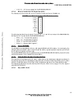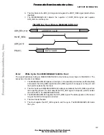
M68360QUADS-040 Hardware User’s Manual
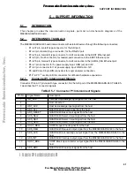
SUPPORT INFORMATION
42
5.2.2
Connector P2 Interconnect Signals
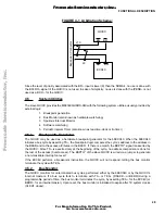
Connector P2 is a 9 pin, female D type connector. It is the RS-232 serial port of the M68360QUADS-040.
TABLE 5-1 describes the P5 connector signals.
5.2.3
Connector P3 Interconnect Signals
Connector P3 is 15 pin, female D type connector. It is the EEST AUI Ethernet port of the M68360QUADS-
040 board. TABLE 5-1 describes the P3 connector signals.
15
-
Not connected
16
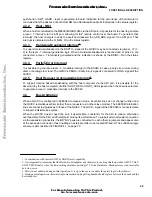
PD1
Bit 1 of the ADI port data bus
17
PD3
Bit 3 of the ADI port data bus
18
PD5
Bit 5 of the ADI port data bus
19
PD7
Bit 7 of the ADI port data bus
20 - 25
GND
Ground signal of the M68360QUADS-040
26
-
Not connected. The host su12V on this pin, but it is not connected on
the M68360QUADS-040
27 - 29
HOST_VCC
HOST VCC input from the host. The M68360QUADS-040 does not use these
inputs for power supply.
30
HOST_ENABLE~
HOST Enable input signal from the host.
31 - 33
GND
Ground signal of the M68360QUADS-040
34
PD0
Bit 0 of the ADI port data bus
35
PD2
Bit 2 of the ADI port data bus
36
PD4
Bit 4 of the ADI port data bus
37
PD6
Bit 6 of the ADI port data bus
TABLE 5-2 Connector P2 Interconnect Signals
Pin No.
Signal Name
Description
1
CD
Carrier Detect output from the M68360QUADS-040.
2
TX
Transmit Data output from the M68360QUADS-040.
3
RX
Receive Data input to the M68360QUADS-040.
4
DTR
Data Terminal Ready input to the M68360QUADS-040.
5
GND
Ground signal of the M68360QUADS-040.
6
DSR
Data Set Ready output from the M68360QUADS-040.
7
RTS (N.C.)
Request To Send. This line is not connected in the M68360QUADS-040.
8
CTS
Clear To Send output from the M68360QUADS-040.
9
-
Not connected
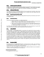
TABLE 5-3 Connector P3 Interconnect Signals
Pin No.
Signal Name
Description
1
GND
Ground signal of the M68360QUADS-040.
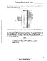
TABLE 5-1 Connector P1 Interconnect Signals
Pin No.
Signal Name
Description
F
re
e
sc
a
le
S
e
m
ic
o
n
d
u
c
to
r,
I
Freescale Semiconductor, Inc.
For More Information On This Product,
Go to: www.freescale.com
n
c
.
..

