M68360QUADS-040 Hardware User’s Manual
Hardware Preparation and Installation
11
2 - Hardware Preparation and Installation
2.1
INTRODUCTION
This chapter provides unpacking instructions, hardware preparation, and installation instructions for the
M68360QUADS-040.
2.2
UNPACKING INSTRUCTIONS
NOTE
If the shipping carton is damaged upon receipt,
request carrier’s agent be present during
unpacking and inspection of equipment.
Unpack equipment from shipping carton. Refer to packing list and verify that all items are present. Save
packing material for storing and reshipping of equipment.
CAUTION
AVOID TOUCHING AREAS OF INTEGRATED
CIRCUITRY; STATIC DISCHARGE CAN
DAMAGE CIRCUITS.
2.3
HARDWARE PREPARATION
To select the desired configuration and ensure proper operation of the M68360QUADS-040 board,
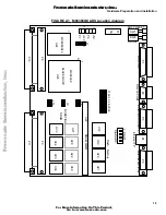
changes of the Dip-Switch settings may be required before installation. The location of the switches, LEDs,
Dip-Switches, and connectors is illustrated in FIGURE 2-1. The board has been factory tested and is
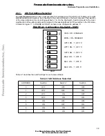
shipped with Dip-Switch settings as described in the following paragraphs. Parameters can be changed for
the following conditions:
•
ADI port address
•
Enable/Disable MC68EC040’s caches (both Instruction and Data)
•
Eanble / Disable MC68LC040’s Memory Management Unit
1
•
Hardware BreakPoint logic operation
•
Parity Error Interrupt generation
•
Arbitration Configuration
•
EEST Twisted Pair Interface configuration
•
User Selectable Options
1. If a MC68
LC
040 device is installed.
F
re
e
sc
a
le
S
e
m
ic
o
n
d
u
c
to
r,
I
Freescale Semiconductor, Inc.
For More Information On This Product,
Go to: www.freescale.com
n
c
.
..


