M68360QUADS-040 Hardware User’s Manual
FUNCTIONAL DESCRIPTION
28
push-button - SW1, HARD - reset is generated to board. Indication for the occurrence of that interrupt is
concluded from the absence of both Host NMI and Hardware-Breakpoint indications in the status register.
4.3.2
Host - NMI
When a host is connected to the M68360QUADS-040 via the ADI port, it is possible for the host to generate
a level - 7 interrupt via the ADI port, allowing for full
1
remote control over the board. To generate that
interrupt, the host computer needs to assert and deassert the ADS_BRK signal of the ADI port. That
interrupt is indicated via the H_NMI~ bit in the status register.
4.3.3
Hardware-Breakpoint Interrupt
2
To support Hardware-Breakpoint, the BKPTO~ signal of the QUICC may be connected via jumper - J7 (1-
2) to the level - 7 interrupt generation logic. When a Hardware Breakpoint is reached and J7 pins 2-3 are
connected, a level - 7 interrupt is generated,and the indication is shown by the BKINT~ bit in the status
register.
4.3.4
Parity
3
Error Interrupt
It is possible to generate a level - 5, maskable interrupt to the EC040 in case a parity error occurs during
dram or bursting sram read. The QUICC’s PERR~ (Parity Error) signal is connected to IRQ5~ signal of the
QUICC.
4.3.5
Host Request / Acknowledge Interrupt
4
To support interrup based handshaking with the host computer via the ADI port, it is possible for the
assertion (by the host computer) of either HOST_REQ or HOST_ACK signals, when the board is selected,
to generate a level 2, maskable interrupt to the EC040.
4.4
Bus Arbitration
When a QUICC is configured in 68EC040 companion mode, its arbiter lines do not change function and
the QUICC remainsbus arbiter (rather than a requester as in other slave modes). The 68EC040 arbitration
lines are connected gluelessly to those of the QUICC. The LOCK~ signal of the 68EC040 is connected also
to support indivisible bus cycles.
When the QUICC doesn’t need the bus, it asserts BG~ constantly for the 040 to reduce arbitration
overhead time for the 040, and therefore improving its performance. To support external master connection
via the expansion connectors, the BR* BG* pairs are connected to each other via jumpers and appear also
at the expansion connector, thus enabling an external arbiter to be located off-board. The arbitration logic
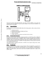
scheme is demonstrated in FIGURE 4-1 on page 29.
1. In conjunction with remote SOFT & HARD resets capability.
2. It is important to remember that the Hardware-Breakpoint and the memory caching shield operation is MUTUALY
EXCLUSIVE, that is, when the data-caching shield is operating (J7 2-3) the Hardware - Breakpoint use is not available
and vice-versa.
3. Parity in not enabled during normal operation. It is up to the users to enable the parity logic to their desire.
4. During normal operation these interrupts are masked and a polling handshake takes place between the board and the
host computer.
F
re
e
sc
a
le
S
e
m
ic
o
n
d
u
c
to
r,
I
Freescale Semiconductor, Inc.
For More Information On This Product,
Go to: www.freescale.com
n
c
.
..


