M68360QUADS-040 Hardware User’s Manual
SUPPORT INFORMATION
55
APPENDIX B - ADI PORT HANDSHAKE DESCRIPTION
B.1
INTRODUCTION
In this appendix, the ADI port signals and the handshake procedure are explained. The M68360QUADS-
040 ADI port can be connected to an ADI board mounted in a host computer.
There are ADI boards for the following host computers:
1.
IBM-PC/XT/AT
2.
SUN - 4 (SBus interface)
B.2
ADI Port Concept and Operation Description
Each ADI board can be connected to up to 8 M68360QUADS-040 boards. Each M68360QUADS-040 has
its own address which is fixed by setting Dip-Switch DSW1 on the board. Refer to section 2.3.1 on page 13.
The following operations can be performed using the ADI port :
•
The host computer can write a byte to the M68360QUADS-040
•
The M68360QUADS-040 can write a byte to the host computer
•
The M68360QUADS-040 can interrupt the host computer
•
The host computer can interrupt the M68360QUADS-040 (interrupt level 7)
•
The host computer can reset (soft or hard) the M68360QUADS-040
If more than one M68360QUADS-040 is connected to the same ADI board, the host computer can perform
the following operations simultaneously on all M68360QUADS-040 boards :
•
Abort all boards (interrupt level 7)
•
Reset all boards
B.3
Handshake Description
Every action between the M68360QUADS-040 and the host is asynchronous and is implemented by
asserting and negating handshake signals by software.
All signals have TTL levels. A control signal is asserted if it is driven to logic ’1’ TTL level, and it is negated
if it is driven to logic ’0’ level.
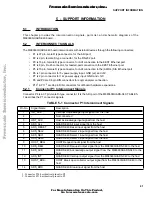
The connection between the host computer and the M68360QUADS-040 is shown in FIGURE B-1 below.
F
re
e
sc
a
le
S
e
m
ic
o
n
d
u
c
to
r,
I
Freescale Semiconductor, Inc.
For More Information On This Product,
Go to: www.freescale.com
n
c
.
..

