M68360QUADS-040 - User’s Manual
Draft 1.0
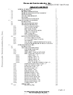
TABLE OF CONTENTS
1 -
GENERAL INFORMATION
7
1.1
INTRODUCTION
7
1.2
RELATED DOCUMENTATION
7
1.3
ABBREVIATIONS USED IN THE DOCUMENT
7
1.4
SPECIFICATIONS
7
1.5
COOLING REQUIREMENTS
8
1.6
FEATURES
9
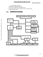
1.7
HARDWARE BLOCK DIAGRAM
10
2 -
Hardware Preparation and Installation
11
2.1
INTRODUCTION
11
2.2
UNPACKING INSTRUCTIONS
11
2.3
HARDWARE PREPARATION
11
2.3.1
ADI Port Address Selection
13
2.3.2
Caches Enable / Disable
14
2.3.3
MMU Enable / Disable
14
2.3.4
Parity Error Interrupt Generation
14
2.3.5 Arbitration
Configuration
14
2.3.6 EEST
Configuration
14
2.3.7
User Selectable Options
14
2.4
INSTALLATION INSTRUCTIONS
14
2.4.1
+5V Power Supply Connection
15
2.4.2
P7: +12V Power Supply Connection
15
2.4.3 ADI
Installation
15
2.4.4
Host computer to M68360QUADS-040 Connection
15
2.4.5
Terminal to M68360QUADS-040 RS-232 Connection
16
3 -
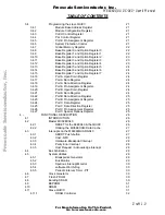
OPERATING INSTRUCTIONS
17
3.1
INTRODUCTION
17
3.2
CONTROLS AND INDICATORS
17
3.2.1
SOFT RESET Switch SW1
17
3.2.2
ABORT Switch SW2
17
3.2.3
HARD RESET - Switches SW1 & SW2
17
3.2.4
EEST Configuration Jumpers J1 to J6
17
3.2.4.1
TPEN Jumper - J1
17
3.2.4.2
APORT Jumper - J2
17
3.2.4.3
TPAPCE Jumper - J3
17
3.2.4.4
TPSQEL Jumper - J4
17
3.2.4.5
TPFULDL Jumper - J5
18
3.2.4.6
LOOP - Diagnostic Loopback Jumper - J6
18
3.2.5
Hardware Breakpoint Usage Jumper - J7
18
3.2.6
Parity Error Interrupt Jumper - J8
18
3.2.7
Bus Request Jumper - J9
18
3.2.8
Bus Grant Jumper - J10
18
3.2.9
HALT Indicator - LD10
18
3.2.10
040RUN Indicator - LD8
18
3.2.11
DMARUN Indicator - LD9
19
3.2.12
Ethernet TX Indicator - LD3
19
3.2.13
Ethernet RX Indicator - LD2
19
3.2.14
Ethernet CLSN Indicator LD4
19
3.2.15
Ethernet LIL Indicator - LD5
19
3.2.16
Ethernet PLR Indicator - LD6
19
3.2.17
Ethernet JABB Indicator - LD1
19
3.2.18
POWER Indicator - LD7
19
3.3
MEMORY MAP
19
3.3.1
Main Memory Map
20
Thi d
t
t d
ith F
M k
4 0 4
F
re
e
sc
a
le
S
e
m
ic
o
n
d
u
c
to
r,
I
Freescale Semiconductor, Inc.
For More Information On This Product,
Go to: www.freescale.com
n
c
.
..


