M68360QUADS-040 Hardware User’s Manual
FUNCTIONAL DESCRIPTION
33
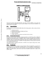
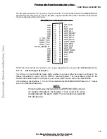
The ADI port connector is a 37 pin, male, D type connector. The connection between the M68360QUADS-
040 and the host computer is by a 37 line flat cable, supplied with the ADI board. FIGURE 4-2 below shows
the pin configuration of the connector.
FIGURE 4-2 ADI Port Connector
NOTE: Pin 26 on the ADI is connected to +12 v power supply, but it is not used in the M68360QUADS-040.
4.11.3.1
ADI Port Signal Description
The ADI port on the QUADS-040 was slightly modified to generate either hard reset or soft reset. This
feature was added to comply with the QUICC’s reset mechanism. The host software written for the
QUADS-040 should be able to work properly with existing ADS boards, such as the M68302ADS.
In the list below, the directions ’I’, ’O’, and ’I/O’ are relative to the M68360QUADS-040 board. (I.E. ’I’ means
input to the M68360QUADS-040)
NOTE:
Since the ADI was originated for the DSP56001ADS, some of
its signals throughout the boards it was used with, were
designated with the prefix “ADS”. This convention is kept with
this design also.
Gnd
20
INT_ACK
1
2
Gnd
21
Gnd
22
Gnd
23
Gnd
24
Gnd
25
(+ 12 v) N.C.
26
HST_ACK
3
ADS_ALL
4
HOST_VCC
ADS_RESET
ADS_SEL2
ADS_SEL1
ADS_SEL0
5
6
7
8
27
HOST_VCC
HOST_VCC
Gnd
Gnd
HOST_ENABLE~
HOST_REQ
ADS_REQ
ADS_ACK
ADS_INT
HOST_BRK~
ADS_BRK
9
10
11
12
13
14
28
29
30
31
32
Gnd
33
PD0
34
PD2
PD4
PD6
N.C.
PD1
PD3
PD5
PD7
15
16
17
18
19
35
36
37
N.C.
F
re
e
sc
a
le
S
e
m
ic
o
n
d
u
c
to
r,
I
Freescale Semiconductor, Inc.
For More Information On This Product,
Go to: www.freescale.com
n
c
.
..

