


1-34
Communications Processor Module (CPM) Ports
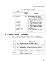
PC27
BRG5O
CLK5
TIMER3/4: TGATE2
Output
Input
Input
Baud-Rate Generator 5 Output
The CPM supports up to 8 BRGs. The BRGs can be used
internally by the bank-of-clocks selection logic and/or provide
an output to one of the 8 BRG pins.
Clock 5
When selected, CLK5 is a source for the SIU timers via
BRG1O. See the
System Interface Unit (SIU)
chapter in the
MSC8101 Technical Reference
manual for additional
information. If CLK5 is not enabled, BRG1O uses an internal
input. If TMCLK is enabled (see PC26 below), the BRG1O
input to the SIU timers is disabled.
Timer 3/4: Timer Gate 2
The timers can be gated/restarted by an external gate signal.
There are two gate signals: TGATE1 controls timer 1 and/or 2
and TGATE2 controls timer 3 and/or 4.
PC26
BRG6O
CLK6
Timer3: TOUT3
TMCLK
Output
Input
Output
Input
Baud-Rate Generator 6 Output
The CPM supports up to 8 BRGs. The BRGs can be used
internally by the bank-of-clocks selection logic and/or provide
an output to one of the 8 BRG pins.
Clock 6
The CPM supports up to 10 clock input pins. The clocks are
sent to the bank-of-clocks selection logic, where they can be
routed to the controllers.
Timer 3: Timer Out 3
The timers (Timer[1–4]) can output a signal on a timer output
(TOUT[1–4]) when the reference value is reached. This signal
can be an active-low pulse or a toggle of the current output.
The output can also connect internally to the input of another
timer, resulting in a 32-bit timer.
Timer Clock
When selected, TMCLK is the designated input to the SIU
timers. When TMCLK is configured as the input to the SIU
timers, the BRG1O input is disabled. See the
System
Interface Unit (SIU)
chapter in the
MSC8101 Technical
Reference
manual for additional information.
Table 1-5. Port C Signals (Continued)
Name
Dedicated
I/O Data
Direction
Description
General-
Purpose
I/O
Peripheral Controller:
Dedicated I/O
Protocol


