


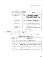


2-8
AC Timings
2.7.2 Reset Timing
The MSC8101 has several inputs to the reset logic:
• Power-on reset (
PORESET
)
• External hard reset (
HRESET
)
• External soft reset (
SRESET
)
Asserting an external
PORESET
causes concurrent assertion of an internal
PORESET
signal,
HRESET
,
and
SRESET
. When the external
PORESET
signal is deasserted, the MSC8101 samples several
configuration pins:
•
RSTCONF
—determines whether the MSC8101 is a master (0) or slave (1) device
•
DBREQ
—determines whether to operate in normal mode (0) or invoke the SC140 debug mode (1)
•
HPE
—disable (0) or enable (1) the host port (HDI16)
•
BTM[0–1]
—boot from external memory (00) or the HDI16 (01)
All these reset sources are fed into the reset controller, which takes different actions depending on the
source of the reset. The reset status register indicates the last sources to cause a reset. Table 2-11
describes reset causes.
2.7.2.1 Reset Operation
The reset control logic determines the cause of a reset, synchronizes it if necessary, and resets the
appropriate logic modules. The memory controller, system protection logic, interrupt controller, and
parallel I/O pins are initialized only on hard reset. Soft reset initializes the internal logic while
maintaining the system configuration. The MSC8101 has two mechanisms for reset configuration: host
reset configuration and hardware reset configuration.
2.7.2.2 Power-On Reset Flow
Asserting the
PORESET
external pin initiates the power-on reset flow.
PORESET
should be asserted
externally for at least 16 input clock cycles after external power to the MSC8101 reaches at least 2/3
V
CC
. As Table 2-12 shows, the MSC8101 has five configuration pins, four of which are multiplexed with
the SC140 core EONCE Event (
EE[0–1]
,
EE[4–5]
) pins and the fifth of which is the
RSTCONF
pin. These
pins are sampled at the rising edge of
PORESET
. In addition to these configuration pins, three
(
MODCK[1–3]
) pins are sampled by the MSC8101. The signals on these pins and the
MODCK_H value
in the Hard Reset Configuration Word determine the PLL locking mode, by defining the ratio between
the DSP clock, the bus clocks, and the CPM clock frequencies.
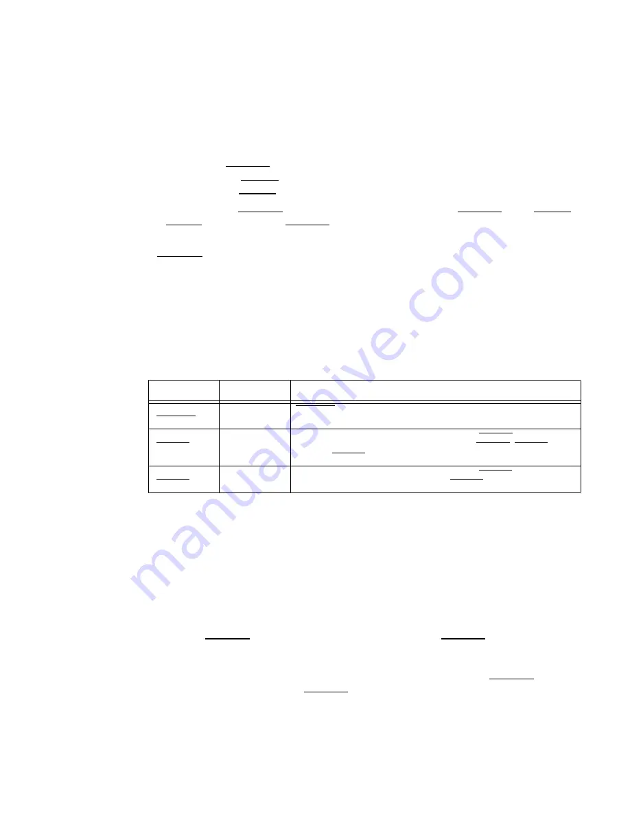
Table 2-11. Reset Causes
Name Direction
Description
Power-on reset
(PORESET)
Input
PORESET initiates the power-on reset flow that resets all the MSC8101s and
configures various attributes of the MSC8101, including its clock mode.
Hard reset
(HRESET)
Input/Output
The MSC8101 can detect an external assertion of HRESET only if it occurs
while the MSC8101 is not asserting reset. During HRESET, SRESET is
asserted. HRESET is an open-drain pin.
Soft reset
(SRESET)
Input/Output
The MSC8101 can detect an external assertion of SRESET only if it occurs
while the MSC8101 is not asserting reset. SRESET is an open-drain pin.


