


2-11
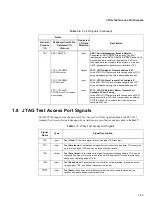
AC Timings
Next, the MSC8101 halts until the SPLL locks. The SPLL locks according to
MODCK[1–3]
, which are
sampled, and to MODCK_H taken from the Reset Configuration Word. SPLL locking time is 800
reference clocks, which is the clock at the output of the SPLL Pre-divider. After the SPLL is locked, all
the clocks to the MSC8101 are enabled. If the DLLDIS bit in the reset configuration word is reset, the
DLL starts the locking process after the SPLL is locked. During PLL and DLL locking,
HRESET
and
SRESET
are asserted.
HRESET
remains asserted for another 512 BUS clocks and is then released. The
SRESET
is released three bus clocks later. If the DLLDIS bit in the reset configuration word is set, the
DLL is bypassed and there is no locking process, thus saving the DLL locking time. Figure 2-4 shows
the power-on reset flow.
2.7.3 System Bus Access Timing
2.7.3.1 Core Data Transfers
Generally, all MSC8101 bus and system output signals are driven from the rising edge of the reference
clock (REFCLK), which is
DLLIN
or, if the DLL is disabled,
CLKOUT
. Memory controller signals,
however, trigger on four points within a REFCLK cycle. Each cycle is divided by four internal ticks: T1,
T2, T3, and T4. T1 always occurs at the rising edge of REFCLK (and T3 at the falling edge), but the
spacing of T2 and T4 depends on the PLL clock ratio selected, as Table 2-14 shows.
Figure 2-4. Hardware Reset Configuration Timing
Table 2-14. Tick Spacing for Memory Controller Signals
PLL Clock Ratio
Tick Spacing (T1 Occurs at the Rising Edge of REFCLK)
T2
T3
T4
1:2, 1:3, 1:4, 1:5, 1:6
1/4 REFCLK
1/2 REFCLK
3/4 REFCLK
1:2.5
3/10 REFCLK
1/2 REFCLK
8/10 REFCLK
1:3.5
4/14 REFCLK
1/2 REFCLK
11/14 REFCLK
PORESET
PORESET
Internal
HRESET
Input
SRESET
RSTCONF is sampled for
master/slave determination
MODCK[1–3] are sampled.
MODCK_H bits are ready
for PLL.
HRESET/SRESET are
extended for 512/515 bus
clocks, respectively, from PLL
and DLL Lock time.
In reset configuration mode:
reset configuration sequence
occurs in this period.
PLL locks after
800 SPLLMFCLKs. DLL
locks 3073 bus clocks after
PLL is locked.
When DLL is disabled, reset
period is shortened by 3073
bus clocks.
Output (I/O)
Output (I/O)
1
asserted for
min 16
CLKIN.
2
3
4
PLL locked
DLL locked
5
6


