


5 - 122 WiNG 5.5 Access Point System Reference Guide
5.2.7.2 Auto IPSec Tunnel
Profile Security Configuration
IPSec tunnels are established to secure traffic, data and management traffic, from access points to remote wireless controllers.
Secure tunnels must be established between access points and the wireless controller with minimum configuration pushed
through DHCP option settings.
1. Select the
Configuration
tab from the Web UI.
2. Select
Devices
.
3. Select
System Profile
from the options on left-hand side of the UI.
4. Expand the
Security
menu and select
Auto IPSec Tunnel
.
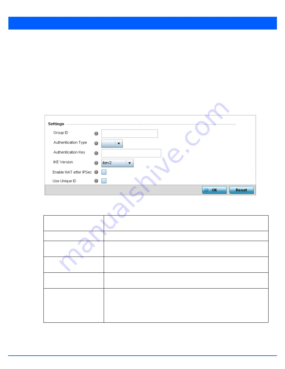
Figure 5-72
Profile Security – Auto IPSec Tunnel screen
5. Refer to the following table to configure the Auto IPSec Tunnel settings:
6. Select
OK
to save the updates made to the
Auto IPSec Tunnel
screen. Selecting
Reset
reverts the screen to its last saved
configuration.
Group ID
Configure the ID string used for IKE authentication. String length can be between 1 - 64
characters.
Authentication Type
Set the IPSec Authentication Type. Options include
PSK
(Pre Shared Key) or
rsa.
Authentication Key
Set the common key for authentication between the remote tunnel peer. Key length is
between 8 - 21 characters.
IKE Version
Configure the IKE version to use. The available options are
ikev1-main
,
ikev1-aggr
and
ikev2.
Enable NAT after IPSec
Select this option to enable NAT after IPSec. Enable this option if there are NATted
networks behind VPN tunnels.
Use Unique ID
In scenarios where different access points behind different NAT boxes/routers have the
same IP address, it is not possible to create a tunnel between the wireless controller
and access point, as the wireless controller fails to identify the access point uniquely.
When selected, each access point behind the same NAT box/router will have a unique
ID. This unique ID is used to create the VPN tunnel.
Содержание AP-7131 Series
Страница 1: ...Motorola Solutions WiNG 5 5 ACCESS POINT SYSTEM REFERENCE GUIDE ...
Страница 2: ......
Страница 3: ...MOTOROLA SOLUTIONS WING 5 5 ACCESS POINT SYSTEM REFERENCE GUIDE MN000160A01 Revision A October 2013 ...
Страница 14: ...x WiNG 5 5 Access Point System Reference Guide ...
Страница 22: ...8 WiNG 5 5 Access Point System Reference Guide ...
Страница 26: ...1 4 WiNG 5 5 Access Point System Reference Guide ...
Страница 74: ...3 36 WiNG 5 5 Access Point System Reference Guide ...
Страница 411: ...Device Configuration 5 325 Figure 5 211 Mesh Point Auto Channel Selection Path Method Root Path Metric screen ...
Страница 428: ...6 2 WiNG 5 5 Access Point System Reference Guide Figure 6 1 Configuration Wireless menu ...
Страница 528: ...6 102 WiNG 5 5 Access Point System Reference Guide ...
Страница 610: ...8 40 WiNG 5 5 Access Point System Reference Guide ...
Страница 615: ...Services Configuration 9 5 Figure 9 2 Captive Portal Policy screen Basic Configuration tab ...
Страница 656: ...9 46 WiNG 5 5 Access Point System Reference Guide ...
Страница 670: ...10 14 WiNG 5 5 Access Point System Reference Guide ...
Страница 682: ...11 12 WiNG 5 5 Access Point System Reference Guide ...
Страница 721: ...Operations 12 39 Figure 12 40 Certificate Management Import New Trustpoint screen ...
Страница 738: ...12 56 WiNG 5 5 Access Point System Reference Guide ...
Страница 890: ...A 2 WiNG 5 5 Access Point System Reference Guide ...
Страница 952: ...B 62 WiNG 5 5 Access Point System Reference Guide ...
Страница 953: ......


