


283
In a character frame, only the data bits carry information. The start bit, check bit, and end bit are used
to facilitate the transmission of the data bits to the destination device. In practical applications, you
must set the data bits, parity check bits, and end bits consistently.
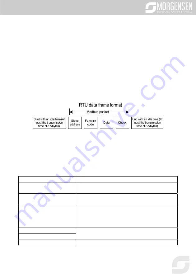
In RTU mode, the transmission of a new frame always starts from an idle time (the transmission time
of 3.5 bytes). On a network where the transmission rate is calculated based on the baud rate, the
transmission time of 3.5 bytes can be easily obtained. After the idle time ends, the data domains are
transmitted in the following sequence: slave address, operation command code, data, and CRC check
character. Each byte transmitted in each domain includes 2 hexadecimal characters (0–9, A–F). The
network devices always monitor the communication bus. After receiving the first domain (address
information), each network device identifies the byte. After the last byte is transmitted, a similar
transmission interval (the transmission time of 3.5 bytes) is used to indicate that the transmission of
the frame ends. Then, the transmission of a new frame starts.
The information of a frame must be transmitted in a continuous data flow. If there is an interval greater
than the transmission time of 1.5 bytes before the transmission of the entire frame is complete, the
receiving device deletes the incomplete information, and mistakes the subsequent byte for the address
domain of a new frame. Similarly, if the transmission interval between two frames is shorter than the
transmission time of 3.5 bytes, the receiving device mistakes it for the data of the last frame. The CRC
check value is incorrect due to the disorder of the frames, and thus a communication fault occurs.
The following table describes the standard structure of an RTU frame.
START (frame header)
T1-T2-T3-T4 (transmission time of 3.5 bytes)
ADDR (slave address domain)
Communication address: 0–247 (decimal system) (0 is the
broadcast address)
CMD (function domain)
03H: read slave parameters
06H: write slave parameters
DATA (N-1)
...
DATA (0)
(data domain)
Data of 2×N bytes, main content of the communication as well
as the core of data exchanging
CRC CHK (LSBs)
Detection value: CRC (16 bits)
CRC CHK high bit (MSBs)
END (frame tail)
T1-T2-T3-T4 (transmission time of 3.5 bytes)
Содержание MSI350 Series
Страница 1: ...MSI350 SERIES INVERTER USER MANUAL...
Страница 2: ...2...
Страница 34: ...34 4 2 6 Vertical installation Fig 4 5 Vertical installation...
Страница 38: ...38 Fig 4 10 3PH 380V 30 37kW Fig 4 11 3PH 380V 45 110kW Fig 4 12 660V 22 45kW...
Страница 39: ...39 Fig 4 13 660V 55 132kW Fig 4 14 380V 132 200kW and 660V 160 220kW...
Страница 40: ...40 Fig 4 15 380V 220 315kW and 660V 250 355kW...
Страница 71: ...71...
Страница 83: ...83 When selecting customized V F curve function users can set the reference channels and...
Страница 90: ...90...
Страница 96: ...96...
Страница 101: ...101...
Страница 147: ...147...
Страница 260: ...260 7 6 Analysis on common faults 7 6 1 Motor fails to work...
Страница 261: ...261 7 6 2 Motor vibrates...
Страница 262: ...262 7 6 3 Overvoltage...
Страница 263: ...263 7 6 4 Undervoltage...
Страница 264: ...264 7 6 5 Unusual heating of motor...
Страница 265: ...265 7 6 6 Inverter overheating...
Страница 266: ...266 7 6 7 Motor stalls during ACC...
Страница 267: ...267 7 6 8 Overcurrent...
Страница 318: ...318 The following figure shows the external wiring of the extension card used in combination with a push pull encoder...
Страница 336: ...336 A 6 5 PROFINET communication card EC TX509...
Страница 339: ...339 A 7 Programmable extension card function description A 7 1 Programmable extension card EC PC501 00...
Страница 380: ...380...
Страница 386: ...386...
Страница 387: ...387...
Страница 388: ...388...