


Page 56
Voyager User’s Manual - EDIT Mode
Page 57
Voyager User’s Manual - EDIT Mode
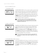
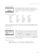
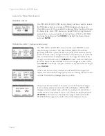
MIDI Control Number (MIDI CTRL NO.): The Touch Surface inputs can transmit user-selected MIDI
CC Messages. For each of the X, Y and A axes, the Touch Surface Inputs can be set to transmit
MIDI CCs 1-31, or it can transmit no MIDI information (OFF). If you are using the Voyager with a
sequencer, then you’ll want to transmit the CC numbers that corresponds to the Touch Surface
Destinations. If you are using the Touch Surface Inputs to control other MIDI devices, then you can
choose the MIDI CC numbers appropriate to the parameters you wish to control in that device.
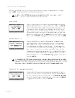
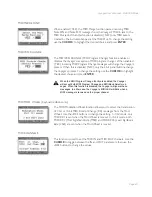
Polarity (DIRECTION): This selects a direction for the Touch Surface inputs to modulate the
destination. The assignable values are NORMAL or INVERTED. For the X and Y axis, ‘NORMAL’
means a voltage changing from -5 to +5 increases the destination’s value, while ‘INVERTED’ means
a voltage changing from +5 to -5 decreases the destination’s value. For the Area (A) parameter,
‘NORMAL’ means a voltage changing from 0 to +5 increases the destination’s value, ‘INVERTED’
means a voltage changing from 0 tp +5 decreases the destination’s value.
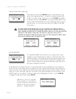
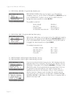
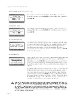
TS AMOUNT: This parameter sets the amount of Touch Surface modulation of the destination. The
assignable values are OFF, 25%, 50%, and 100%. Each axis can be set independently. ‘OFF’ means that
axis does not modulate the destination. ‘50%’ means that the amount of the touch surface output
adds 50% of the total range of that control to its present value. For example, if the TSX destination
is set to ‘Filter Cutoff’ and the amount is set to 50%, when the filter
CUTOFF
control knob is fully
counter clockwise, the maximum TSX value (all the way to the right of the TS panel) would make a
change in the filter cutoff equal to turning the
CUTOFF
knob to the mid-position (in other words,
about 50%). When the amount is set to ‘100%’, the Touch Surface output equals the full range of the
destination’s control.
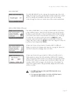
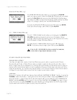
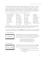
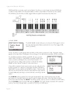
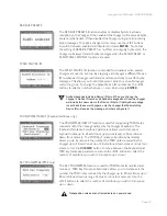
LFO Sample & Hold (LFO S&H): This function allows the X, Y and A control signals to be sampled
at the rate set by the Sample and Hold Gate (normally the LFO square wave), providing a new and
innovative way to use the Touch Surface.
Use the
-1/+1
buttons to switch the LFO S&H function ON or
OFF. The control menus for the Touch Surface X, Y and A signals are
identical, and each can have the S&H function switched ON or OFF
individually.
For more on using the Touch Surface LFO S&H function, see
Appendix A.
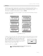
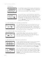
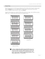
The LFO S&H function is the fifth option in the Touch Surface menu. Since the Touch Surface menu
can only display four options at a time, use the
CURSOR
to scroll down to the bottom of the list,
where the LFO S&H option will appear:
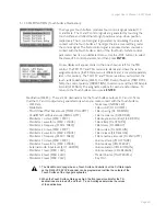
Although the RME has no Touch Surface Controller, the XYA & Gate inputs on the RME
VX-352 CV Expander can be programmed just like the outputs of the Touch Surface of the
Voyager keyboards.


