


Page 36
Voyager User’s Manual - The Components
Page 37
Voyager User’s Manual - The Components
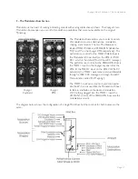
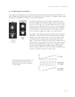
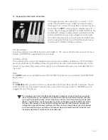
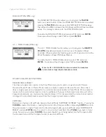
LFO/Sample and Hold Section Controls
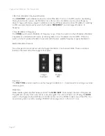
LFO Rate:
The
LFO RATE
control sets the rate of the dedicated LFO. The control range is 0.2 to 50 Hz.
LFO Sync:
The
LFO SYNC
control selects the trigger method for starting the LFO waveform. There are four trigger
modes:
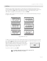
- OFF/SYNC: This setting allows the LFO to be free running unless there is a
connection to the LFO SYNC input (see below).
- MIDI: This setting allows the division of the MIDI clock signal (set up in the EDIT
mode function ‘MIDI CLK Divider’) to retrigger the LFO. Note that the LFO is
an analog circuit, and does not automatically sync to MIDI clock; it is restarted
much in the manner of oscillator sync, and does not defeat the Rate control.
- KB (Keyboard): This setting allows the LFO to be retriggered when a MIDI ‘Note On’
message is received.
- ENV. GATE: This setting allows an input to the Envelope Gate Source jack (part of
the Envelope CV inputs) to restart the LFO.
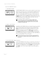
Additional CV Control
(applies to all Voyager keyboards and the RME with the VX-352 CV Input Expander only):
LFO Rate:
The
LFO RATE
jack accepts an expression pedal or a control voltage from -5 to +5V. A positive voltage
here adds to the position of the LFO RATE control, while a negative voltage will subtract from the position
of the
LFO RATE
control.
The S&H GATE jack will only work with a +5V Gate input, not a footswitch.
LFO Sync:
The
LFO SYNC
jack accepts a footswitch or a +5V Gate input. Closing the footswitch or applying a gate
here will retrigger the LFO waveform.
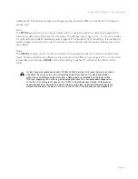
S&H In (Sample and Hold Input):
The
S&H IN
jack accepts an expression pedal or a control voltage from -5 to +5V. The voltage on this jack
is the signal source for the Sample and Hold circuit input.
S&H Gate (Sample and Hold Gate):
The
S&H GATE
jack accepts a +5V Gate input. Applying a gate signal here will trigger the Sample and Hold
circuit.
By applying an external voltage to the LFO RATE jack you can control the LFO
frequency well beyond the specified range. Rates lower than one cycle per minute
are possible, as are frequencies that go well into the audio range.


