


Page 32
Voyager User’s Manual - The Components
Page 33
Voyager User’s Manual - The Components
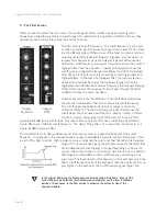
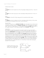
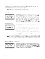
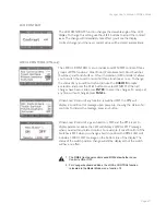
Destination:
The
DESTINATION
control selects the destination of the modulation. The modulation destination is cho-
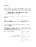
sen in the same manner as the source. The modulation destination selections are:
- PITCH (the pitch of all three oscillators)
- OSC2 (the pitch of Oscillator 2 only)
- OSC3 (the pitch of Oscillator 3 only)
- FILTER (the Cutoff Frequency of the filter)
- WAVE (the waveforms of all 3 oscillators)
- LFO/PGM: This is a programmable destination for the Mod Bus; LFO Rate is the
default. Programmable Mod destinations are set in the EDIT mode using the
menu functions ‘PGM M-WHL DEST’ (Programmable Mod Wheel Destination)
and ‘PGM PEDAL DEST’ (Programmable Pedal Destination).
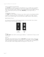
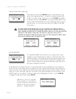
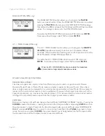
Amount:
The
AMOUNT
control is used to set the maximum amount of modulation that is sent to the modulation
destination. When the
AMOUNT
control is set to 0, no modulation will pass. When the
AMOUNT
is
set to 10, the maximum amount of modulation is sent to the destination when the performance controller
(Mod Wheel or MOD1 level) is all the way up.
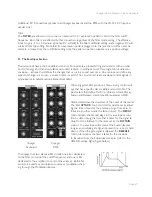
Related Controls:
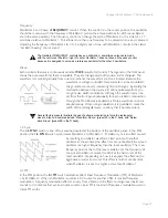
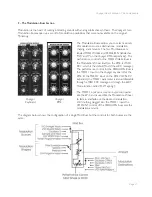
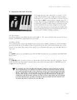
Mod Bus Performance Controllers:
The Mod Wheel and MOD 1 Input are performance controllers for the Mod Wheel Modulation Bus and
Pedal/ON bus respectively. These performance controllers are the final stage in determining the amount
of modulation sent to the selected destination. When these controllers are set to maximum, the modula-
tion amount is determined by the AMOUNT control. When these controllers are set to 0, the modulation
amount is 0.
1. Although the RME has no built-in performance controllers, the Mod Wheel from a
MIDI controller keyboard will produce the same result as described here, providing it
is sending MIDI CC1 messages.
2. For the RME, the MOD 1 Input is only available if the optional VX-352 CV Expander
is connected. Without the VX-352 connected, the Pedal Bus will default to ‘ON’.