


Page 92
Voyager User’s Manual - Appendices
Page 93
Voyager User’s Manual - Appendices
Connecting the VX351 and VX-352:
Make all connections as described below with the Voyager powered OFF
1) If your are using the VX-351 with a Voyager keyboard, the first step is to install the VX-351 output
adapter. Refer to the installation guide for this procedure. The output adapter MUST be installed in
these units to ensure proper operation of the VX-351.
2) To connect the VX-351, locate the male end (the end with recessed pins) of the DB-25 cable - this
is the end that plugs into the connector on the Voyager’s back panel labeled “ACCESSORY PORT”
(this is the “OUTPUT ACCESSORY PORT” on the RME). Align the cable properly and make the
connection. Use the thumbscrews to lock the connection. Be careful not to force or cross thread
the thumbscrews in the accessory port’s female threads. Following this, connect the other end of the
cable to the connector on the VX-351 labeled “FROM ACCESSORY PORT”.
3) To connect the VX-352, locate the male end (the end with recessed pins) of the DB-25 cable
- this is the end that plugs into the connector on the Voyager RME’s back panel labeled “INPUT
ACCESSORY PORT”. Align the cable properly and make the connection. Use the thumbscrews to
lock the connection. Be careful not to force or cross thread the thumbscrews in the accessory port’s
female threads. Following this, connect the other end of the cable to the connector on the VX-352
labeled “FROM ACCESSORY PORT”.
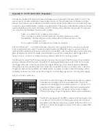
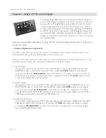
Now let’s start with a basic sound and see how the VX-351 and VX-352 can work with the Voyager.
- Power up the Voyager keyboard or RME
- Press the
EDIT
button.
- In the EDIT menu select ‘INIT PARAMETERS’, press
ENTER
, select ‘YES’ and press
ENTER
again.
This loads the default Voyager sound.
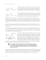
- Using a 1⁄4“ patch cord, plug one end into the VX-351’s LFO triangle output. Plug the other end
into the Voyager keyboard Filter Control Input (or the Filter Cutoff jack if using the VX-352).
- Play a note on the Voyager and you will hear the LFO modulating the Filter’s Cutoff. Adjusting the
Voyager’s
LFO RATE
control will change the rate that the Filter Cutoff moves up and down. This
demonstrates a basic patch with the VX-351/VX-352.
- Now disconnect the cable from the Voyager’s Filter Control (the Filter Cutoff jack if using the VX-
352) and connect it to the IN of one of the VX-351 Attenuators. Set the Attenuator amount to
zero. Using another 1⁄4” cable, make a connection from the VX-351 Attenuator OUT to the Filter
Control Input (or Filter Cutoff jack on the VX-352).
- Play a note and gradually increase the Attenuator amount. You will notice that the amount of
modulation will increase. An Attenuator is used to set the amount of a CV Source that passes to
the Destination.
The RME does not require the VX-351 output adapter to be installed.
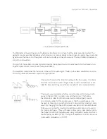
As you make CV and Gate connections, think of the output jacks as your Sources (like the LFO
triangle wave in the above example), and the input jacks as your Destinations (like the Filter
Control Input in the above example).


