


Page 76
Voyager User’s Manual - MIDI
Page 77
Voyager User’s Manual - MIDI
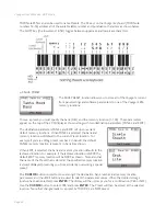
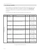
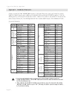
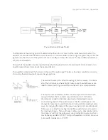
How the Voyager handles MIDI
When you adjust any one of the Voyager’s front panel controls, MIDI Continuous Controller (CC) mes-
sages are transmitted on the MIDI Out jack. The information contained in these MIDI messages varies
according to the parameter each edit control is assigned. For example, when the
FILTER CUTOFF
control is rotated, MIDI CC data corresponding to the Filter Cutoff parameter (CC#19 & CC#51) is
transmitted.
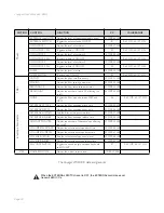
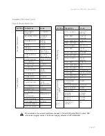
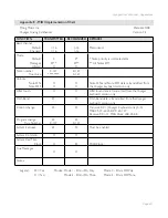
The following chart lists the MIDI CC data that is generated for each front panel control.
SECTION
CONTROL
FUNCTION
CC
VALUE/RANGE
Modulation Busses
MW SOURCE
Selects the Mod Wheel bus source modulation
68
0-15 = Tri
16-31 = Square
32-47 = Osc 3
48-63 = S&H
64-79 = ON/Mod2
80-127 = Noise/PGM
MW DESTINATION
Selects the Mod Wheel bus destination
69
0-15 = Pitch
16-31 = Osc 2
32-47 = Osc 3
48-63 = Filt
64-79 = Wave
80-127 = LFO Rate/PGM
MW SHAPING
Selects the Mod Wheel bus modulation shaping
70
0-31 = Filt
32-63 = Velocity
64-95 = Aftertouch
96-127 = ON/PGM
MW AMOUNT
Adjusts the Mod Wheel bus modulation amount
6 MSB, 38 LSB
-
PEDAL SOURCE
Selects the Pedal/ON bus source modulation
71
0-15 = Tri
16-31 = Square
32-47 = Osc 3
48-63 = S&H
64-79 = ON/Mod2
80-127 = Noise/PGM
PEDAL DEST.
Selects the Pedal/ON bus destination
72
0-15 = Tri
16-31 = Square
32-47 = Osc 3
48-63 = S&H
64-79 = ON/Mod2
80-127 = Noise/PGM
PEDAL SHAPING
Selects the Pedal/ON bus modulation shaping
73
0-31 = Filt
32-63 = Velocity
64-95 = Aftertouch
96-127 = ON/PGM
PEDAL AMOUNT
Adjusts the Pedal/ON bus modulation amount
8 MSB, 40 LSB
-
The Voyager’s MIDI CC data assignments