


Page 104
Voyager User’s Manual - Appendices
Page 105
Voyager User’s Manual - Appendices
To produce a modulated filter effect:
Using a patch cord, connect the CP-251 Attenuator Output to the Voyager’s FILTER jack (or the
FILTER CUTOFF jack on the VX-352). On the CP-251, set the LFO
RATE
control to 6 Hz (about
1 o’clock), and adjust the
ATTENUATOR
to about ‘2’ on the dial. This will produce a cyclical tonal
variation as the filter cutoff frequency is modulated. Setting the CP-251’s LFO
RATE
control
considerably higher will result in wild timbral textures, while a very low setting will create a slowly
evolving filter sweep.
2. Inverting the keyboard CV to the Filters
This is a handy little trick that can be used to lower the filter cutoff as you play higher on the keyboard. This
is similar to certain acoustic instruments like a cello, whose tone gets duller as higher notes are played.
- Initialize the Voyager’s parameters.
- Turn the Voyager Filter
KB. CONT. AMOUNT
control to ‘0’
- Using a patch cord, connect the VX-351 KBD PITCH output to the CP-251 Attenuator Input.
- With a second patch cord, connect the Attenuator output to the Voyager’s FILTER jack (or the
FILTER CUTOFF jack on the VX-352).
- Set the CP-251’s
ATTENUATOR
control level to -5.
Play a scale up the keyboard, from low to high, and you’ll notice that the sound gets much duller. Adjust the
ATTENUATOR
control to taste.
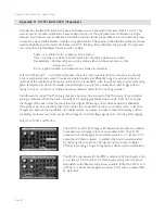
3. Creating Sample and Hold staircase patterns
A Sample and Hold circuit can be used for more than generating random voltages. One type of modulation
pattern that can be achieved is called “Staircase” modulation. It is achieved by feeding a slow triangle wave
into the Sample and Hold circuit and sampling that input at a high rate, effectively chopping the triangle
wave into discreet voltage levels that resembles a staircase. We’ll use two LFO’s for this; a slow one for the
input and a fast one for the trigger.
- Initialize the Voyager’s parameters. Set the Voyager’s LFO rate to about .4 Hz.
- Using a patch cable, connect the VX-351’s LFO triangle output to the Voyager’s Sample
and Hold Input (S&H IN).
- Set the CP-251’s LFO rate to about 6 Hz (about 1 o’ clock on the dial).
- Using another patch cable, connect the CP-251’s LFO square wave output to the Voyager’s
Sample and Hold Gate Input (S&H GATE).
- Set the Voyager’s MOD WHEEL MOD BUSS
SOURCE
control to ‘S&H’.
Play a note and move the Mod Wheel forward. You should hear the pitch modulated by an ‘up & down’
staircase waveform.
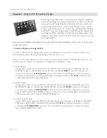
There may be times when you want a wider control range than a single CV provides. It’s
possible to increase the control range of a CV using a Mult and the Mixer in the CP-251.
Begin by connecting the CV to a Mult, and then make connections from the Mult to the
Mixer 1 & Mixer 2 inputs. Set the Mixer 1 & 2, and Master levels to maximum, then route
the output to your desired input. (Note: Although the Mixer is effectively doubling the CV
signal in this configuration, the Mixer output cannot exceed about +/-7.5V)


