Page 56
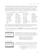
Voyager User’s Manual - EDIT Mode
Page 57
Voyager User’s Manual - EDIT Mode
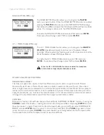
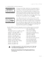
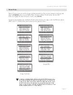
- External Audio On/Off switch
(EXTERNAL AUDIO)
- Osc.1 On/Off switch (OSCILLATOR 1)
- Osc.2 On/Off switch (OSCILLATOR 2)
- Osc. 3 On/Off switch (OSCILLATOR 3
- Noise On/Off switch (NOISE SWITCH)
- Filter Mode switch (FILTER MODE)
- Envelope Gate switch
(ENV GATE SWITCH)
- No Switch
- Glide Switch
- Release Switch
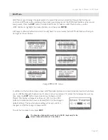
- Oscillator 1-2 Sync switch
(OSC 1-2 SYNC)
- Oscillator 3-1 FM switch (OSC 3-1 FM)
- Oscillator 3 Keyboard Control switch
(OSC 3 KB CTRL)
- Oscillator 3 Frequency Range switch
(OSC 3 FREQUENCY)
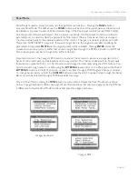
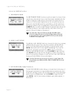
Touch Surface Gate Menu:
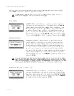
The TS Gate menu allows you to select the gate control (T.S GATE
CONTROL), the MIDI Control number (MIDI CTRL NO.) the gate
polarity (POLARITY), and the LFO Restart function. The assignable
options for these parameters are listed below.
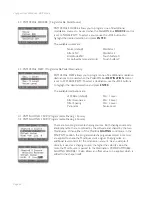
Gate Controls: There are 14 destinations for the Touch Surface Gate output parameter. ‘NO
SWITCH’ is the default destination:
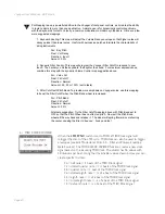
1. The S&H Gate signal is the LFO Square Wave normalled to the S&H Gate Input connection
on the VX-352. If nothing is connected to the S&H Gate Input jack, the sample rate of the
TS LFO S&H function is controlled by the RME’s LFO.
2. The Touch Surface sample is actually taken on both the rising and falling edges of the LFO
Square Wave, which means that the actual sample rate of the TS LFO S&H is double the LFO
rate (or double the rate of an external S&H Gate signal, if connected).
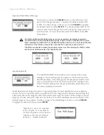
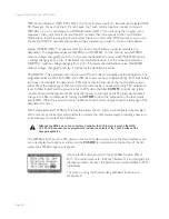
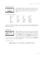
MIDI Control Number (MIDI CTRL NO.): The Touch Surface Inputs can transmit user-selected MIDI
CC Messages. The T.S. Gate Input can transmit MIDI CCs 64-127, where 0 = OFF and 64 = ON, or
it can transmit no MIDI information (OFF).
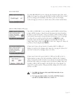
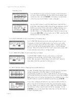
Polarity: This selects the direction for the Touch Surface inputs to effect the destination. The
assignable values are NORMAL or INVERTED. ‘NORMAL’ means the gate signal turns a switch
ON
(Note: If ‘3 KB CONT’ is the selected destination, the Gate will turn the 3 KB CONT switch
OFF when the NORMAL polarity is selected). When the Gate is OFF (no contact with the Touch
Surface), the switch is OFF. ‘INVERSE’ means a Gate Signal from the Touch Surface turns the
destination switch OFF, and when the Gate is OFF, the switch is ON.

