Page 100
Voyager User’s Manual - Appendices
Page 101
Voyager User’s Manual - Appendices
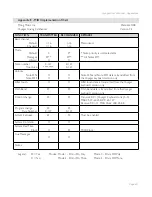
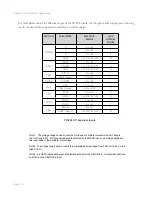
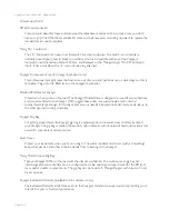
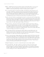
VX-351 CV OUTPUT EXP
ANDER
SOURCE
DESTINA
TION
Touch X
Touch
Y
Touch
A
Touch Gate
KBD Pitch
KBD
Velocity
KBD Pressure
KBD Gate
Pitch
Wheel
Mod
Wheel
MOD1
MOD2
LFO
Tr
iangle
LFO Square
Mod
Wheel Mod Bus
Pedal/On Mod Bus
Filter En
v
Vol En
v
S&H Step
S&H Smooth
Noise
ATTEN.
1/Amount
ATTEN.
2/Amount
Mult
A1
Mult
A2
Mult
A3
Mult
A4
Mult B1
Mult B2
Mult B3
Mult B4
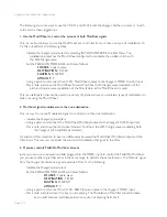
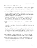
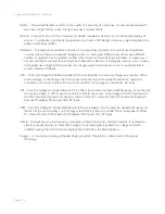
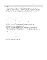
Documenting your work
One thing to keep in mind is that although the Voyager can remember the settings of the front panel
controls as a preset, it cannot save the routings of patch cables or the positions of the attenuators. We
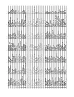
recommend having a list of the Expander connections with space to document routings like so:
VX-352 CV INPUT EXP
ANDER
SOURCE
RME DESTINA
TION
Touch X
Touch
Y
Touch
A
Touch Gate
ENV Gate
ENC Release
ENV Rate
OSC Pitch
OSC
W
av
e
FIL
TER Cutoff
OUT
Volume
OUT P
an
LFO Rate
LFO Sync
MOD Mod1
MOD Mod2
S&H Input
S&H Gate
ATTEN 1 In (Amount/Offset)
ATTEN 2 In (Amount/Offset)
ATTEN 1 Out
ATTEN 2 Out
Mult 1
Mult 2
Mult 3
Mult 4


