


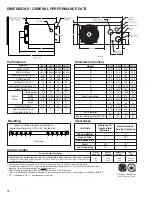


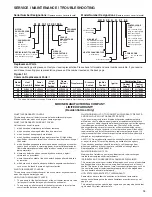


7
7
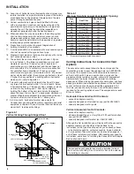
Installing the Concentric Vent Adapter Box
1.
Determine the location of the box. Refer to the instructions
in the following sections for the method of venting to be
used (vertical or horizontal). Maintain all clearances as
listed in these instructions.
2.
This box can be mounted flush to the wall or roof, or the box
can be offset from the wall or roof by using field supplied
brackets. When mounting the box, consider serviceability
and access to the vent and combustion air pipes.
3.
If the box is to be mounted using field supplied brackets,
these brackets must be strong enough to rigidly secure the
box to the wall or roof, and should be made from corrosion
resistant material. After determining the length of the field
supplied brackets, attach them to the sides of the box using
several corrosion resistant sheet metal screws. See Figure
7.1 for typical installation and brackets.
Figure 7.1
Adapter Box Assembly with Vent Outlet Pipe Attached
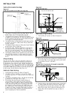
5.
Determine the appropriate length of vent pipe that must be
attached to the vent outlet (the concentric side) of the box.
Refer to Table 5.1 for the horizontal concentric venting and
vertical concentric venting minimum length of vent pipe to
be used for the method of venting (vertical or horizontal).
Make sure to add the length of the field supplied brackets
if used, and the thickness of the wall or roof.
6.
Cut the vent pipe to the proper length and attach it to the
vent outlet of the concentric vent adapter box using at
least 3 corrosion resistant sheet metal screws. Seal the
joint and seam using metallic tape or silastic suitable for
temperatures up to 350° F. Wrap the tape two full turns
around the vent pipe. See Figure 7.1.
7.
Determine the length of the combustion air pipe to extend
through the wall. Refer to the horizontal concentric venting
and vertical concentric venting sections for the minimum
length of combustion air pipe to be used for the method of
venting being used, vertical or horizontal. Cut the pipe to
the proper length.
8.
Slide the combustion air pipe over the vent pipe and seal
the joints and seam with a metallic tape or silastic suitable
for temperatures up to 350˚F (3M tapes 433 or 363 are
acceptable). Wrap the tape two full turns around the vent
pipe. Attach the combustion air pipe to the adapter box
using at least 3 non corrosive sheet metal screws. See
Figure 7.2
Figure 7.2
Adapter Box Assembly with Combustion Air Pipe Attached
9.
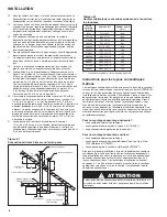
Place this assembly (the adapter box, vent pipe and
combustion air pipe) through the wall or roof and verify
that the distance requirements as defined in the following
sections are met. Securely attach the assembly (adapter
box and vent and combustion air pipe).
10. For model sizes 30 and 45, place the 3” to 4” vent
transitions on the non-concentric side and attached with 3
corrosion resistant fasteners.
Horizontal Concentric Venting:
Figure 7.3
Horizontal Concentric Vent (rear pipe hidden)
1.
The vent pipe must terminate with the terminal supplied by
the manufacturer for horizontal venting. Refer to the parts
list on page 6 for the appropriate part.
2.
The combustion air pipe must terminate at least 1 inch
from the wall. This will prevent water from running down the
wall and into the pipe and allows for easy installation of the
combustion air intake guard.
3.
Caulk between the wall and the air intake pipe.
4.
Maintain 14 inches from the combustion air inlet to the back
of the vent terminal.
5.
Attach the combustion air intake guard using non corrosive
screws as shown in Figure 7.2. This guard must be placed
at the end of the pipe on the exterior of the building. This
guard helps to prevent animals and debris from entering
the combustion air pipe.
Table 7.1
Concentric Vent Adapter Box Dimensions
Outlet Vent Pipe Attached
Field Supplied
Mounting Brackets
B
C
A
Outlet Vent
Pipe Attached
Combustion Air
Pipe Attached
Combustion Air
Intake Guard
Building Side Wall
Outlet Vent
Termination Cap
Combustion Air
Intake Guard
A B C
Outlet
Inlet Outlet Inlet
30,45 8.25" 11.75" 4"
4"
4"
4"
6"
60,75
Model
Size
Non Concentric
Size
Concentric
Side
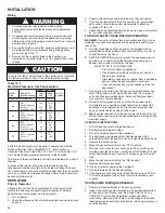
INSTALLATION


