


12
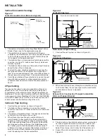
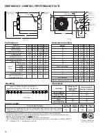
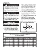
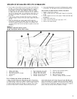
DIMENSIONS / GENERAL PERFORMANCE DATA
Certified for Residential
and Commercial Use
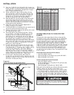
Top and Bottom
1"
1"
Access
Side
1"
18"
Non-Access Side
1"
1"
Rear
18" 18"
Vent
Connector
4" 4"
HDS30 HDS45 HDS60 HDS75
30,000
45,000 60,000 75,000
24,000 36,000 48,000 60,000
505 720 990 1,160
523 749 653 769
44 46 45 48
10 10 12 14
25 27 36 38
1/25 1/15 1/12 1/12
1,550 1,550 1,625 1,625
S.P.
S.P. P.S.C. P.S.C.
1.5 2.4 1.2 1.2
2.8 3.7 2.5 2.5
3 3 4 4
Models
Btu/Hr Input
Btu/Hr Output
Entering Airflow (CFM)
Outlet Velocity
Air Temp. Rise (°F)
Mounting Height (Max ft.)
Heat Throw (ft.)
Unit Total Amps
Vent/Combustion air
Connector Size (in.)
Performance
Horsepower
RPM
Type
Amps
Motor
Data
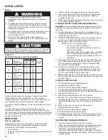
HDS30 HDS45 HDS60 HDS75
26.8 26.8 26.8 26.8
12.2 12.2 18.0 18.0
16.5 16.5 16.5 16.5
14.9 14.9 14.9 14.9
10.1 10.1 15.9 15.9
7.25
7.25 10.75 10.75
18.5 18.5 18.5 18.5
7.6
7.6 7.835 7.835
1/2 1/2 1/2 1/2
34.5 34.5 34.5 34.5
22 22 25 25
2.74 2.74 3.15 3.15
3.19 3.19 5.55 5.55
10 10 14 14
55 60 80 85
Models
A
B
C
D
E
F
G
H
Gas Connection
I
J
K
L
Fan Diameter
Approx. Shipping Weight (lbs.)
Dimensions (inches)
• Ratings shown are for elevation up to 2000 feet above sea level (in Canada, refer to rating plate).
For elevations above 2000 ft., ratings should be reduced by approximately 4% for each 1000 ft. above sea level.
• Mounting Height is measured from the bottom of the unit.
• Heat Throws are calculated at 65°F ambient and unit fired at full rated input.
Throws for HDS30 and HDS45 are based on 8-foot mounting heights and at 10-foot heights for HDS60 and HDS75.
• S.P. = shaded pole, P.S.C. = permanent split capacitor
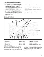
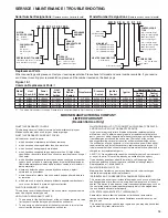
Control Codes
Single Stage, Hot Surface Ignition, 100% Shut-Off, Multiple Retry with Auto Reset from Lockout.
-
Utilizes a single-stage combination gas control with built-in ignition control. Gas is lit with a hot
surface igniter on call for heat.
34
74
115V
115V
24V
24V
natural
propane
Control System Description
Control
Code No.
Service
Voltage
Thermostat
Voltage
Type of
Gas
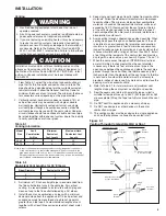
Clearances
Unit Side
Clearance To
Combustible
Materials
Recommended
Service Clearance
1” - angle, mounting brackets are slotted to
accommodate joists on 16” or 24” centerlines.
25.10
23.10
21.10
19.10
17.10
9.10
7.10
5.10
3.10
1.10
0.00
Top View
Mounting


