Modine Manufacturing HDS Скачать руководство пользователя страница 11

11

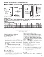
CONTROL OPERATING SEQUENCE
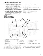
Figure 11.1
Major Gas, Electrical Service,
Safety and Other Components


For series 103, the time delay relay is located on the terminal board.

For Hot Surface Ignition

Upon a call for heat from the thermostat, power is supplied to 
the power exhauster motor. The unit will go through a purge 
period and then the hot surface igniter will be energized. After 
the igniter has warmed up, the main valve in the combination 
control valve will open to allow gas to flow to the burners. If the 

fan motor has not already started it will start shortly. If a flame 
is not sensed for any reason the main valve will close and there 
will be a short purge period before ignition is tried again. If the 
flame is not sensed after four tries there will be at least a one 
hour wait before ignition is tried again.

1. Wiring 

Diagram

2. Power 

Exhauster

3. 

LED Dignostic Codes

4. Pressure 

Switch

5. Terminal 

Board

6. Control 

Transformer

7. 

Serial Plate (hidden)

8. 

Flame Sensor (hidden)

9. 

Flame Rollout Switch

10.  Limit Control (hidden)


15

14

13

12

11

11.   Hot Surface Igniter (hidden)
12. Gas Orifi ces
13. Mounting Brackets
14.  Combination Gas Control
15.  Common Replacement Parts (hidden)

3.   In so far as practical, close all building doors and windows 

and all doors between the space in which the appliance(s) 
connected to the venting system are located and other 
spaces of the building. Turn on clothes dryers and any 
exhaust fans such as range hoods and bathroom exhausts, 
so they shall operate at maximum speed. Do not operate a 
summer exhaust fan. Close fireplace dampers.

4.  Follow the lighting instructions. Place the appliance being 

inspected in operation. Adjust thermostat so that the 
appliance will operate continuously.

5.   After it has been determined that each appliance connected 

to a venting system properly vents when tested as outlined 
above, return doors, windows, exhaust fans, fireplace 
dampers and any other gas-burning appliance to their 
previous conditions of use.

6.  If improper venting is observed during any of the above 

tests, the venting system must be corrected.

TO TURN OFF GAS TO APPLIANCE

1.  Set thermostat to lowest setting.
2  Turn manual shut-off valve located outside of the unit to the 

closed position.

3.  Turn off all electric power to the appliance if service is to be 

performed. 

4.  Remove access panel.
5.  Turn the gas valve switch to the “OFF” position.
6.   Replace the access panel.

Содержание HDS

Страница 1: ...nd commercial applications WARNING Improper installation adjustment alteration service or maintenance can cause property damage injury or death and could cause exposure to substances which have been determined by various state agencies to cause cancer birth defects or other reproductive harm Read the installation operating and maintenance instructions thoroughly before installing or servicing this...

Страница 2: ...ndicated on the serial plate must not be less than 5 below the rated input or 5 below the minimum rated input of duel rated units 11 Ensure that the supply voltage to the appliance as indicated on the serial plate is not 5 greater than the rated voltage CAUTION 1 Installation must conform with local building codes or in the absence of local codes with Part 7 Venting of Equipment of the National Fu...

Страница 3: ...nce with the current CSA B149 1 codes 4 In aircraft hangars keep the bottom of the unit at least 10 from the highest surface of the wings or engine enclosure of the highest aircraft housed in the hangars and in accordance with the requirements of the enforcing authority and or NFPA 409 latest edition 5 Installation of units in high humidity or salt water atmospheres will cause accelerated corrosio...

Страница 4: ...er in Standard Mounting Configuration For right hand the mounting brackets are attached in a similar manner after the unit is turned over 5a Suspension by screws lag bolts Secure the mounting brackets to the ceiling joists or truss using 1 4 screws with 1 2 washers These 1 angle mounting brackets are slotted to accommodate joists on 16 or 24 centerlines 5b Suspension by threaded rod This heater ca...

Страница 5: ...t less than 350 F Install a tee fitting at the low point of the vent system and provide a drip leg with a clean out cap as shown in Figures 7 2 and 7 3 7 When the vent passes through an INTERIOR wall or floor a metal thimble 4 inches greater than the vent diameter is necessary If there is 6 feet or more of vent pipe in the open space between the appliance and where the vent pipe passes through the...

Страница 6: ...that 2 to adjacent buildings Size according to expected snow depth Venting Instructions for Concentric Vent Options The concentric vent concept allows for the vent pipe and the combustion air pipe to pass through one hole in an EXTERIOR wall or roof The concentric vent kits offered are horizontal or vertical Venting with 2 pipes a combustion air pipe and flue product vent pipe remains an option pr...

Страница 7: ...used vertical or horizontal Cut the pipe to the proper length 8 Slide the combustion air pipe over the vent pipe and seal the joints and seam with a metallic tape or silastic suitable for temperatures up to 350 F 3M tapes 433 or 363 are acceptable Wrap the tape two full turns around the vent pipe Attach the combustion air pipe to the adapter box using at least 3 non corrosive sheet metal screws Se...

Страница 8: ... least 1 foot above and 6 inches horizontally from the combustion air inlet 4 When the vent passes through a combustible roof a metal thimble 4 inches greater than the vent diameter is necessary If there are 6 feet or more of vertical vent pipe in the open space between the unit heater and where the vent pipe passes through the roof the thimble need only be 2 inches greater than the diameter of th...

Страница 9: ...nual shut off valve is gas tight on an anual basis 4 Provide a sediment trap before each unit in the line where low spots cannot be avoided See Figure 9 1 5 When Pressure Leak testing pressures above 14 W C 1 2 psi close the field installed shut off valve disconnect the appliance and its combination gas control from the gas supply line and plug the supply line before testing When testing pressures...

Страница 10: ...AS Do not try to light any appliance Do not touch any electric switch do not use any phone in your building Immediately call your gas supplier from a neighbors phone Follow the gas supplier s instructions If you cannot reach your gas supplier call the fire department C Use only your hand to move the gas control switch Never use tools If the switch will not move by hand don t try to repair it call ...

Страница 11: ... Mounting Brackets 14 Combination Gas Control 15 Common Replacement Parts hidden 3 In so far as practical close all building doors and windows and all doors between the space in which the appliance s connected to the venting system are located and other spaces of the building Turn on clothes dryers and any exhaust fans such as range hoods and bathroom exhausts so they shall operate at maximum spee...

Страница 12: ...ection I J K L Fan Diameter Approx Shipping Weight lbs Dimensions inches Ratings shown are for elevation up to 2000 feet above sea level in Canada refer to rating plate For elevations above 2000 ft ratings should be reduced by approximately 4 for each 1000 ft above sea level Mounting Height is measured from the bottom of the unit Heat Throws are calculated at 65 F ambient and unit fired at full ra...

Страница 13: ...lified service agency 2 Do not attempt to reuse any mechanical or electrical controllers which have been wet Replace defective controller WARNING When servicing or repairing of this equipment use only factory approved service replacement parts A complete replacement parts list may be obtained by contacting the factory Refer to the rating plate on the appliance for complete appliance model number s...

Страница 14: ...5V 60Hz 1Ø Power Shown 115V 60Hz 1Ø Power Circuit Breaker By Others L1 BK L2 W R Flame Rollout Switch R R G TR1 TR2 Flame Rollout Switch Wiring Diagram Selection Since internal or factory wiring may vary depending on controls manufacturer the wiring diagrams must be selected with the series identity number when installing servicing or troubleshooting a unit heater control system Wiring diagrams th...

Страница 15: ... years from the date you purchased the unit heater 2 The warranty on all other parts of the heater remains in force for two years from the date you purchased the unit heater WHAT MODINE WILL DO TO CORRECT ANY WARRANTY DEFECTS AND HOW YOU CAN GET WARRANTY SERVICE In the event of warranty failure Modine will provide replacement parts at Modine s cost To obtain warranty repairs or replacement of defe...

Страница 16: ...REACH AS LIMITED HEREIN SHALL BE LIMITED TO ONE YEAR FROM DATE OF SHIPMENT FROM SELLER Heat Exchanger Condensers for all Seller s products except non separated combustion Gas Fired Unit Heaters and Infrared Heaters all Burners except Infrared Heaters and Sheet Metal for all Seller s products BUYER S REMEDY FOR BREACH OF WARRANTY EXCLUSIVE OF ALL OTHER REMEDIES PROVIDED BY LAW IS LIMITED TO REPAIR ...

Страница 17: ...STALLATION N OUBLIEZ PAS DE LE LAISSER AU PROPRIÉTAIRE EN QUITTANT LE CHANTIER Inspection à la réception 1 Inspectez l appareil à la livraison Signalez immédiatement tout dommage au transporteur et avisez le représentant commercial local de Modine 2 Vérifiez la plaque signalétique pour déterminer si les caractéristiques de l appareil correspondent à l alimentation électrique disponible au point d ...

Страница 18: ...t calorifique minimal du gaz utilisé au niveau de la mer ne doit pas être inférieur de plus de 5 à la valeur nominale minimale inscrite sur la plaque signalétique de l appareil 11 Vérifiez que la tension d alimentation de l appareil n excède pas de plus de 5 la tension nominale d alimentation inscrite sur la plaque de l appareil ATTENTION 1 L installation doit respecter les codes locaux de la cons...

Страница 19: ... de l échangeur de chaleur AUCUN appareil chauffé au gaz ne devrait être installé dans des locaux dont l atmosphère contient des vapeurs corrosives chlorées halogénées ou acides ATTENTION 1 Les appareils de chauffage à profil bas sont conçus pour des applications avec des températures ambiantes comprises entre 40 C et 32 C 2 L appareil n est pas conçu pour être installé à l extérieur 3 Dans les ga...

Страница 20: ... droite fixez les ferrures de la même manière après avoir inversé l appareil 5a Suspension par des vis ou des tirefonds Fixez les ferrures de montage aux solives du plafond ou aux fermes du toit en utilisant des vis 6 35 mm et des rondelles 12 7 mm Ces ferrures sont des cornières de 25 4 mm encochées pour s adapter à des solives aux espacements standard de 406 4 ou de 609 6 mm 5b Suspension par ti...

Страница 21: ...ge avec regard de nettoyage au point le plus bas du système d évacuation comme illustré aux figures 7 2 et 7 3 7 Si le tuyau traverse une cloison ou un plancher INTÉRIEUR la traversée doit être munie d un manchon métallique ayant un diamètre de 10 cm 4 po de plus que le tuyau Si le tuyau situé entre l appareil et la traversée du mur ou du plancher a une longueur supérieure à 1 8 m 6 pi le manchon ...

Страница 22: ...Le chapeau de la cheminée ne doit pas se terminer à moins de 0 60 m 2 pi d un bâtiment adjacent Il faut tenir compte de la couche de neige prévisible Instructions pour les tuyaux concentriques Options Le montage concentrique permet de faire passer le tuyau d évacuation et le tuyau d air de combustion par un même trou dans le mur EXTÉRIEUR ou dans le toit Des ensembles de tuyaux concentriques exist...

Страница 23: ...ngueur voulue 8 Enfilez le tuyau d air autour du tuyau d évacuation et assurez l étanchéité avec du ruban métallique ou du Silastic convenant pour des températures jusqu à 177 C 350 F Les rubans 3M références 433 et 363 sont acceptables Le ruban doit être enroulé deux fois autour du tuyau Fixez le tuyau d air de combustion à la boîte adaptatrice avec au moins 3 vis à tôle anticorrosion Voir la fig...

Страница 24: ...air de combustion 4 Si la cheminée traverse un toit combustible ce dernier doit être protégé par un manchon de 10 cm 4 po plus grand que le diamètre de la cheminée Si la longueur du tuyau vertical passant dans l espace vide entre l appareil et la traversée du toit est 1 8 m 6 pi ou plus le manchon peut avoir un diamètre de 5 cm 2 po seulement de plus que le tuyau S il n y a pas de manchon de trave...

Страница 25: ...es points bas sur la tuyauterie de gaz il faut ajouter un collecteur de sédiments en amont de chaque appareil Voir la figure 9 1 5 Si des essais de pression et d étachéité doivent être faits à plus de 3 36 kPa d eau 0 5 psi fermez le robinet d arrêt débranchez l appareil et son régulateur de gaz combiné de la tuyauterie d alimentation et bouchez la tuyauterie avant de procéder à l essai Pour des p...

Страница 26: ...chauffe ou si le gaz ne s arrête plus fermez le robinet d arrêt manuel avant de couper l alimentation électrique de l appareil INSTRUCTIONS D UTILISATION 1 AVANT D ALLER PLUS LOIN Lisez les informations de sécurité ci dessus 2 Réglez le thermostat au minimum 3 Coupez l alimentation électrique de l appareil 4 L appareil est équipé d un dispositif d allumage automatique de la veilleuse du brûleur N ...

Страница 27: ...rures de montage 14 Régulateur de gaz combiné 15 Pièces de rechange courantes cachées 3 Dans la mesure du possible fermez toutes les portes et fenêtres du bâtiment ainsi que les portes de communication entre les espaces dans lesquels se trouvent le ou les appareils reliés au système d évacuation et les autres zones du bâtiment Mettez en marche au régime maximum les sécheuses de linge et tous les v...

Страница 28: ...signalétique Si l altitude est supérieure à 600 m 2000 pi les valeurs nominales doivent être réduites d environ 4 par tranche de 300 m 1000 pi au dessus du niveau de la mer Hauteurs de montage mesurées à partir dudessous de l appareil Portées de chauffage calculées pour une rempérature ambiante de 18 C 65 F et au plein régime nominal Portées pour les HDS30 et HDS45 basées sur une hauteur de montag...

Страница 29: ... de commande mécaniques ou électriques qui ont été atteints par de l eau Remplacez tout contrôleur défectueux 13 ENTRETIEN MAINTENANCE DÉPANNAGE AVERTISSEMENT Pour l entretien et les réparations de cet appareil n utilisez que des pièces d origine approuvées Pour la liste complète des pièces de rechange adressez vous au fabricant Le numéro de modèle complet le numéro de série et l adresse du fabric...

Страница 30: ...Mono Shown Secteur 115V 60Hz Mono Disjoncteur autre source L1 BK L2 W R Détecteur de retour de flamme R R G TR1 TR2 Détecteur de retour de flamme Choix du schéma de câblage Le câblage posé en usine et le câblage interne sont parfois différents selon le modèle des organes de commande installés et il est important de choisir le schéma approprié d après le numéro de série pour l installation l entret...

Страница 31: ...iode de dix ans à compter de la date d achat de l appareil 2 Tous les autres éléments de l appareil sont garantis pendant une période de deux ans à compter de la date d achat WHAT MODINE WILL DO TO CORRECT ANY WARRANTY DEFECTS AND HOW YOU CAN GET WARRANTY SERVICE En cas de défaillance sous garantie Modine fournira les pièces de rechange nécessaires à la réparation à son prix coûtant Pour obtenir d...

Страница 32: ... produits offerts par leVendeur sauf les appareils de chauffage et les appareils infrarouges chauffés au gaz à combustion non séparée tous les brûleurs sauf ceux des appareils infrarouges et les pièces en tôle utilisées dans tous les produits offerts par leVendeur LE RECOURS DE L ACHETEUR EN CAS DE DÉFAILLANCE SOUS GARANTIE À L EXCLUSION DETOUS LES REMÈDES PRÉVUS PAR LA LOI EST LIMITÉ À LA RÉPARAT...

Отзывы: