


1. From Table 5.1, select the size of vent and combustion air
pipe that fits the flue outlet and combustion air intake. The
pipe should be galvanized steel or other suitable corrosion
resistant material. Follow the National Fuel Gas Code for
minimum thickness of vent material. The minimum thickness
for connectors varies depending on the pipe diameter.
2. Vertically vented (horizontal run does not exceed 75% of
vertical rise) units may be vented with single or double
wall vent pipe. Horizontally vented units must use single
wall vent pipe although one continuous section of double
wall vent pipe may be used with the vent system. Under no
circumstances should two sections of double wall vent pipe
be joined together within one vent system due to the inability
to verify complete seal of inner pipes.
Note: A vent is the vertical passageway used to convey flue gases from the unit
or the vent connector to the outside atmosphere. A vent connector is the
pipe which connects the unit to a vent or chimney. Vent connectors serving
Category I appliances shall not be connected into any portion of mechanical
draft systems operating under positive pressure.
3. A minimum of 12 inches straight pipe is recommended from
the flue outlet before turns in the vent pipe. For vertical
venting, it is recommended to install a tee with drip leg and
clean out cap to the flue outlet followed by a 90° elbow.
4. Install the vent and combustion air pipes with a minimum
downward slope from the appliance of 1/4 inch per foot and
suspend securely from overhead structures at no points
greater than 3 feet apart. Fasten individual lengths of vent
together with at least three corrosion resistant sheet metal
screws.
5. Keep single wall vent pipe at least 6 inches from combustible
materials. Follow the double wall manufacturer’s clearances
to combustibles. The minimum distance from combustible
materials is based on the combustible material surface not
exceeding 160°F. Clearance from the vent pipe (or the top
of the unit) may be required to be greater than 6 inches if
heat damage other than fire (such as material distortion or
discoloration) could result.
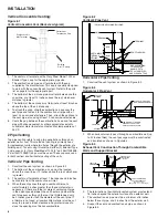
6. Avoid venting through unheated space when possible. When
venting does pass through an unheated space or if the unit
is installed in an environment that promotes condensation,
insulate runs greater than 5 feet to minimize condensation.
Inspect for leakage prior to insulating and use insulation that
is noncombustible with a rating of not less than 350°F. Install
a tee fitting at the low point of the vent system and provide a
drip leg with a clean out cap as shown in Figures 7.2 and 7.3.
7. When the vent passes through an INTERIOR wall or floor,
a metal thimble 4 inches greater than the vent diameter
is necessary. If there is 6 feet or more of vent pipe in the
open space between the appliance and where the vent pipe
passes through the wall or floor, the thimble need only be 2
inches greater than the diameter of the vent pipe. If a thimble
is not used, all combustible material must be cut away to
provide 6 inches of clearance. Any material used to close the
opening must be noncombustible.
8.
Refer to Table 5.1 for total minimum and maximum vent
lengths making the vent system as straight as possible.
9.
Seal the seams and joints with a metallic tape or silastic
suitable for temperatures up to 350°F. (3M tapes 433 or 363
are acceptable.) Wrap the tape two full turns around the vent
pipe.
10. Do NOT vent this appliance into a masonry chimney.
11. Do NOT use dampers or other devices in the vent or
combustion air pipes.
12. The venting system must be exclusive to a single appliance,
and no other appliance is allowed to be vented into it.
5
INSTALLATION
WARNING
1. Gas fired heating equipment must be vented - do not
operate
unvented.
2. A built-in power exhauster is provided - additional external
power exhausters are not required or permitted.
3. If you are replacing an existing heater, it may be necessary
to resize the venting systems. Improperly sized venting
systems can result in vent gas leakage or the formation of
condensate. Refer to the National Fuel Gas Code ANSI
Z223.1 or CSA B149.1 latest edition. Failure to follow these
instructions can result in serious injury or death.
CAUTION
Installation must conform with local building codes or in the
absence of local codes, with Part 7, Venting of Equipment, of
the National Fuel Gas Code, ANSI Z223.1 (NFPA 54) - latest
edition. In Canada installation must be in accordance with
CSA B149.1
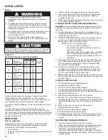
Venting
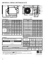
Table 5.1
Venting Information
Model Vent/
Minimum Maximum
Horz.
Size
Combination
Equivalent
Equivalent
Vent
Air Size
Vent Length
Length
30,45
3"
3'
25'
60,75
4"
3'
25'
Table 5.2
Equivalent Vent Lengths for 90° Elbows
Elbow Diameter
Equivalent Length
3"
1'
4"
5'
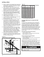
Figure 5.1
Venting Through Combustible Wall or Roof
Listed
Terminal
Flashing
Listed
Thimble
Listed
Terminal
Flashing
Clearance Specified
by Type B Vent Mfg.
Listed
Thimble
Single Wall Vent Pipe
Double Wall Vent Pipe
Single Wall Vent Pipe Terminating
with Double wall vent pipe.
Single Wall Vent Pipe
Double
Wall
Single
Wall
Specified
Terminal
Clearance Specified
by Type B Vent Mfg.
Single
Wall
Specified
Terminal


